2 3 SLIDEOUT SYSTEM OPERA TION AND SERVICE MANUAL PERATION X
TABLE OF CONTENTS SYSTEM……………………………........….….. Warning……..……………........…….... Description…….…………........…….. Prior to Operation…………………… 3 3 3 4 OPERATION…………………........…………… Main Components......................... Mechanical........................... Electrical.............................. Operating System......................... Extending Slideout ...........… Retracting Slideout ..........… Manual Operation....…...…… Preventative Maintenance…......... 5 5 5 6 7 7 7 8 9 SERVICE………………………..…....
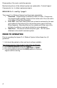
SYSTEM WARNING FAILURE TO ACT IN ACCORDANCE WITH THE FOLLOWING MAY RESULT IN SERIOUS PERSONAL INJURY OR DEATH. The Lippert 2 x 3 Slideout System is intended for the sole purpose of extending and retracting the slideout room. Its function should not be used for any other purpose or reason than to actuate the slideout room. To use the system for any reason other than what it is designed for may result in damage to the coach and/or cause serious personal injury or even death.
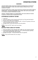
Disassembly of the motor voids the warranty. Mechanical portions of the slideout system are replaceable. Contact Lippert Components, Inc. to obtain replacement parts. WELD-ON 2 x 3 – see Fig. 1 page 5 The Lippert 2 x 3 Slideout System has three basic assemblies: 1. Outer Rail – Angled flange is welded to frame of coach. Flange runs from approximately halfway forward of the inside end of the outer rail to outer edge of Gear Drive Assembly. 2.
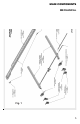
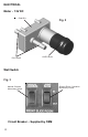
MAIN COMPONENTS MECHANICAL Fig.
ELECTRICAL Motor - 12V DC Gear Box Drive Shaft Fig. 2 12VDC Motor Wall Switch Fig.
OPERATING SYSTEM WARNING ALWAYS MAKE SURE THAT THE SLIDEOUT ROOM PATH IS CLEAR OF PEOPLE AND OBJECTS BEFORE AND DURING OPERATION OF THE SLIDEOUT ROOM. ALWAYS KEEP AWAY FROM THE SLIDE RAILS WHEN THE ROOM IS BEING OPERATED. THE GEAR ASSEMBLY MAY PINCH OR CATCH ON LOOSE CLOTHING CAUSING PERSONAL INJURY. INSTALL TRANSIT BARS (IF SO EQUIPPED) ON THE SLIDEOUT ROOM DURING STORAGE AND TRANSPORTATION. EXTENDING SLIDEOUT ROOM 1. 2. 3. 4.
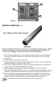
A C B Fig. 4 MANUAL OPERATION Fig. 5-Manual Override Coupler WARNING! Always disconnect battery from system prior to manually operating system. Failure to disconnect battery can cause electricity to backfeed through the motor and cause serious damage to the system as well as void the warranty. 1. Prior to Manual Operation, be sure slideout area is clear of any obstructions that may impede the extention or retraction of the slideout room, including transit bars. 2. Locate slideout mechanism under unit.
WARNING! The gears can be stripped out if the room is manually retracted/extended to it’s fullest extent and the operator continues to rotate manual override. Any damage due to misuse of the Manual Override feature will disqualify any and all claims to the Limited Warranty. PREVENTATIVE MAINTENANCE The Lippert 2 x 3 Slideout System has been designed to require very little maintenance. To ensure the long life of your slideout system, read and follow these few simple procedures.
SERVICE TROUBLESHOOTING The Lippert 2 x 3 Slideout System is only one of four inter-related slideout room system components. These four components are as follows: chassis, slideout room, coach and Lippert 2 x 3 Slideout System. Each one needs to function correctly with the others or misalignment problems will occur. Every coach has it’s own personality and what may work to fix one coach may not work on another even if the symptoms appear to be the same.
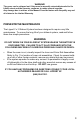
DO NOT LOOSEN Fig. 6a - Timing Adadpter 1/4-20 Nut (NOT SHOWN) 1 2 DO NOT LOOSEN 1/4-20 x 1 5/16 3 1/4-20 x 1 5/16 3 1/4-20 x 1 5/16 4 Fig.
INSTRUCTIONS FOR ADJUSTMENT OF ROOM. The Lippert 2 x 3 Slideout System can be timed and fine-tuned for optimum performance. In the event the travel of either side of this two-rail system should be out of time, follow this process for re-timing the slide-out room. Note: When addressing issues regarding your slide-out room, remember to relay the information from the OUTSIDE of the coach. This note will help to standardize the information needed to be relayed to a service station or technical service at LCI.
TROUBLESHOOTING CHART The folowing troubleshooting chart outlines some common problems, their causes and possible corrective actions. When reference is made to a “Power Unit,” the term includes the motor and the actuator as a complete unit. All Power Units are shipped from the factory with a serial number and date code, which should be given to the service technician when asking for assistance.
Switch related problems: • If room moves opposite from what the switch plate indicates, reverse the motor wires on the back of the switch (refer to the wiring diagram page 15). Wire size must be 10ga. Min. WARNING! – HIGH VOLTAGE • • If a gear is stripped, the entire gearbox must be replaced. If the room does not seal fully, refer to page 13. TROUBLESHOOTING – MOTOR Before attempting to troubleshoot the Motor, make sure an adequate power source is available.
ORDERING PARTS To assist the customer service when ordering parts, please provide the following information: 1. Your Name 2. Company Name 3. Phone Number 4. Shipping Address 5. Billing Address 6. Purchase Order Number 7. Coach A. Serial # and/or VIN # B. Make C. Model 8. Part Number 9. Description 10. Quantity Please take your coach to an authorized service center for repairs.