
Manual
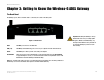
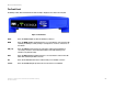
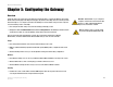
Table Of Contents
- User Guide
- Table of Contents
- List of Figures
- Chapter 1: Introduction
- Chapter 2: Planning your Network
- Chapter 3: Getting to Know the Wireless-G ADSL Gateway
- Chapter 4: Connecting the Wireless-G Broadband Gateway
- Chapter 5: Configuring the Gateway
- Appendix A: Troubleshooting
- Appendix B: Wireless Security
- Appendix C: Configuring IPSec between a Windows 2000 or XP Computer and the Gateway
- Appendix D: Finding the MAC Address and IP Address for Your Ethernet Adapter
- Appendix E: Upgrading Firmware
- Appendix F: Glossary
- Appendix G: Specifications
- Appendix H: Regulatory Information
- Appendix I: Warranty Information
- Appendix J: Contact Information

9
Chapter 3: Getting to Know the Wireless-G ADSL Gateway
The Front Panel
Wireless-G ADSL Gateway
The Front Panel
The Gateway's LEDs, where information about network activity is displayed, are located on the front panel.
Power Green. The Power LED lights up when the Gateway is powered on.
WLAN Green. The WLAN LED lights up whenever there is a successful wireless connection. If the LED
is blinking, the Gateway is actively sending or receiving data to or from one of the devices on
the network.
LAN (1-4) Green. The LAN LED serves two purposes. If the LED is continuously lit, the Gateway is
successfully connected to a device through the LAN port. If the LED is blinking, it is an
indication of any network activity.
ADSL Green. The ADSL LED lights up whenever there is a successful modem connection. The LED
blinks while establishing the ADSL connection.
Act Green. The Act LED blinks when there is network activity across the ADSL connection.
Session Green. The Session LED lights up when a PPPoE or PPPoA session is established.
Figure 3-2: Front Panel