
User Guide
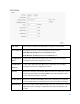
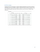
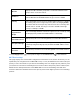
Table Of Contents
- Contents
- Ethernet Switch Features
- System
- L2 Feature
- VLAN
- Management
- ACL
- QoS
- Security
- Monitoring
- Diagnostics
- Maintenance
- Status
- Mode
- Report
- Suppression
32
The Common Instance Spanning Tree (CIST) protocol is formed by the spanning tree algorithm
running among bridges that support the IEEE 802.1w, IEEE 802.1s, and IEEE 802.1D standard.
A Common and Internal Spanning Tree (CIST) represents the connectivity of the entire network
and it is equivalent to a spanning tree in an STP/RSTP.
The CIST inside a Multiple Spanning Tree Instance (MST) region is the same as the CST outside a
region. All regions are bound together using a CIST, which is responsible for creating loop-free
topology across regions, whereas the MSTI controls topology inside regions. CST instances allow
different regions to communicate between themselves. CST is also used for traffic within the
region for any VLANs not covered by a MSTI. In an MSTP-enabled network, there is only one CIST
that runs between MST regions and single spanning tree devices. A network may contain multiple
MST regions and other network segments running RSTP. Multiple regions and other STP bridges
are interconnected using a single CST.
Multiple Spanning Tree Protocol (MSTP) defined in IEEE 802.1s, enables multiple VLANs to be
mapped to reduce the number of spanning-tree instances needed to support a large number of
VLANs. If there is only one VLAN in the network, a single STP works appropriately.
If the network contains more than one VLAN however, the logical network configured by a single
STP would work, but it becomes more efficient to use the alternate paths available by using an
alternate spanning tree for different VLANs or groups of VLANs. MSTP (which is based on RSTP
for fast convergence) is designed to support independent spanning trees based on VLAN groups.
MSTP provides multiple forwarding paths for data traffic and enables load balancing.
STP and RSTP prevent loops from forming by ensuring that only one path exists between the end
nodes in your network. RSTP is designed as a general replacement for the slower, legacy STP.
RSTP is also incorporated into MSTP. With STP, convergence can take up to a minute to complete
in a larger network. This can result in the loss of communication between various parts of the
network during the convergence process so STP can subsequently lose data packets during
transmission.
RSTP on the other hand is much faster than STP. It can complete a convergence in seconds, so it
greatly diminishes the possible impact the process can have on your network compared to STP.
RSTP reduces the number of state changes before active ports start learning, predefining an
alternate route that can be used when a node or port fails and retain the forwarding database for
ports insensitive to changes in the tree structure when reconfiguration occurs.
Select whether to Enable or Disable the Spanning Tree function for the Switch. Next, select
whether you wish to enable STP, RSTP, or MSTP. Again, please note that only one Spanning tree
function can be active at a time.