USER GUIDE BUSINESS SERIES 10/100 4-Port VPN Router Model: RV042
About This Guide About This Guide Icon Descriptions While reading through the User Guide you may see various icons that call attention to specific items. Below is a description of these icons: NOTE: This check mark indicates that there is a note of interest and is something that you should pay special attention to while using the product. Copyright and Trademarks Linksys, Cisco and the Cisco Logo are registered trademarks or trademarks of Cisco Systems, Inc. and/or its affiliates in the U.S.
Table of Contents Chapter 1: Introduction 1 Introduction to the Router . . . . . . . . . . . . . . . . . . . . . . . . . . . . . . . . . . . . . . . . 1 Introduction to VPNs . . . . . . . . . . . . . . . . . . . . . . . . . . . . . . . . . . . . . . . . . . . . 1 VPN Examples . . . . . . . . . . . . . . . . . . . . . . . . . . . . . . . . . . . . . . . . . . . . . . . .
Table of Contents One-to-One NAT . . . . . . . . . . . . . . . . . . . . . . . . . . . . . . . . . . . . . . . . . . . 16 Setup > MAC Clone . . . . . . . . . . . . . . . . . . . . . . . . . . . . . . . . . . . . . . . . . . . . 16 MAC Clone . . . . . . . . . . . . . . . . . . . . . . . . . . . . . . . . . . . . . . . . . . . . . . .17 Setup > DDNS . . . . . . . . . . . . . . . . . . . . . . . . . .
Table of Contents VPN > Client to Gateway . . . . . . . . . . . . . . . . . . . . . . . . . . . . . . . . . . . . . . . . . 40 Add a New Tunnel . . . . . . . . . . . . . . . . . . . . . . . . . . . . . . . . . . . . . . . . . . 41 IPSec Setup . . . . . . . . . . . . . . . . . . . . . . . . . . . . . . . . . . . . . . . . . . . . . . 44 VPN > VPN Client Access . . . . . . . .
Table of Contents Configuration of PC 1 and PC 2 . . . . . . . . . . . . . . . . . . . . . . . . . . . . . . . . . . 63 Configuration when the Remote Gateway Uses a Dynamic IP Address . . . . . . . . . . . 64 Configuration of the RVL200 . . . . . . . . . . . . . . . . . . . . . . . . . . . . . . . . . . . 64 Configuration of the RV042 . . . . . . . . . . . . . . . . . . . . . . . . . . . . . . . .
Table of Contents Appendix I: Warranty Information 82 Exclusions and Limitations . . . . . . . . . . . . . . . . . . . . . . . . . . . . . . . . . . . . . . . 82 Obtaining Warranty Service . . . . . . . . . . . . . . . . . . . . . . . . . . . . . . . . . . . . . . . 82 Technical Support . . . . . . . . . . . . . . . . . . . . . . . . . . . . . . . . . . . . . . . . . . . . .
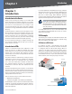
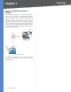
Chapter 1 Chapter 1: Introduction Introduction to the Router Thank you for choosing the Linksys 10/100 4-Port VPN Router. The Router lets multiple computers in your office share an Internet connection. The dual Internet ports let you connect a second Internet line as a backup, or you can use both Internet ports at the same time, allowing the Router to manage bandwidth demands for maximum efficiency.
Chapter 1 Introduction Computer (using VPN client software) to VPN Router The following is an example of a computer-to-VPN Router VPN. In her hotel room, a traveling businesswoman connects to her Internet Service Provider (ISP). Her notebook computer has VPN client software that is configured with her office’s VPN settings. She accesses the VPN client software and connects to the VPN Router at the central office. As VPNs use the Internet, distance is not a factor.
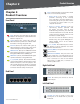
Chapter 2 Chapter 2: Product Overview Front Panel Product Overview Reset The Reset button can be used for a warm reset or a reset to factory defaults. •• Warm Reset If the Router is having problems connecting to the Internet, press and hold in the Reset button for a second using the tip of a pen. This is similar to pressing the power button on your computer to reboot it. •• Reset to Factory Defaults If you are Diag (Red) The Diag LED lights up when the Router is not ready for use.
Chapter 3 Installation Chapter 3: Installation Follow these instructions: 1. Determine where you want to mount the Router. Make sure that the wall you use is smooth, flat, dry, and sturdy. Also make sure the location is within reach of an electrical outlet. Physical Installation There are two ways to place the Router. The first way is to place the Router horizontally on a surface. The second way is to mount the Router on a wall. Horizontal Placement The Router has four rubber feet on its bottom panel.
Chapter 3 2. Connect one end of an Ethernet network cable to one of the numbered ports on the back of the Router. Connect the other end to an Ethernet port on a network device, such as a computer or switch. Installation 5. Connect the included power adapter to the Router’s Power port, and then plug the power adapter into an electrical outlet. Repeat this step to connect more computers or other network devices to the Router. Connect the Power 6.
Chapter 4 Chapter 4: Advanced Configuration Overview The Router’s web-based utility allows you to set up the Router and perform advanced configuration and troubleshooting. This chapter will explain all of the functions in this utility. Advanced Configuration System Summary The first screen that appears is the System Summary screen, which displays the Router’s current status and settings. This information is read-only.
Chapter 4 Advanced Configuration System Up Time This is the length of time in days, hours, and minutes that the Router has been active. The current time and date are also displayed. Trend Micro™ ProtectLink Gateway The optional Trend Micro ProtectLink Gateway service provides security for your network. It checks e-mail messages, filters website addresses (URLs), and blocks potentially malicious websites.
Chapter 4 Advanced Configuration DDNS It shows the DDNS settings of the Router’s WAN port(s) and hyperlinks to the Setup > DDNS screen. DMZ Host It shows the DMZ private IP address and hyperlinks to the Setup > DMZ Host screen. The default is Disabled. Firewall Setting Status SPI (Stateful Packet Inspection) It shows the status (On/Off ) of the SPI setting and hyperlinks to the Firewall > General screen.
Chapter 4 Advanced Configuration be sent out, probably use incorrect settings,” will be displayed. Setup Tab > Network The Network screen shows all of the Router’s basic setup functions. The Router can be used in most network setups without changing any of the default values; however, you may need to enter additional information in order to connect to the Internet through an ISP (Internet Service Provider) or broadband (DSL or cable) carrier. The setup information is provided by your ISP.
Chapter 4 If you want to modify a subnet you have created, select it and make changes. Click Save Settings to save your changes, or click Cancel Changes to undo them. Click Exit to return to the Network screen. If you want to delete a subnet you have created, select it and click Delete selected subnet. Click Save Settings to save your changes, or click Cancel Changes to undo them. Click Exit to return to the Network screen. You can also divide a Class C network into four subnets.
Chapter 4 Advanced Configuration Service Name Enter the Service Name, if provided by your ISP. Connect on Demand If you select the Connect on Demand option, the connection will be disconnected after a specified period of inactivity (Max Idle Time). If you have been disconnected due to inactivity, Connect on Demand enables the Router to automatically re-establish your connection as soon as you attempt to access the Internet again.
Chapter 4 Advanced Configuration Default Gateway Address Enter the IP address of the default gateway. User Name and Password Enter your account’s User Name and Password. The maximum number of characters is 60. Connect on Demand If you select the Connect on Demand option, the connection will be disconnected after a specified period of inactivity (Max Idle Time).
Chapter 4 Advanced Configuration Daylight Saving To use the daylight saving feature, select Enabled. Enter the Month and Day of the start date, and then enter the Month and Day of the end date. NTP Server Enter the URL or IP address of the NTP server. The default is time.nist.gov. Manual Setup > Password Password The User Name is admin; it cannot be changed. Old Password Enter the old password. The default is admin when you first power up the Router. New Password Enter a new password for the Router.
Chapter 4 Setup Tab > Forwarding The Forwarding screen allows you to set up port range forwarding and port triggering applications. Port range forwarding can be used to set up public services or other specialized Internet applications on your network, while port triggering can be used to set up triggered ranges and forwarded ranges for Internet applications. Advanced Configuration Enable Select Enable to enable this port range forwarding entry.
Chapter 4 Advanced Configuration Some Internet applications or games use alternate ports to communicate between the server and LAN host. When you want to use these applications, enter the triggering (outgoing) port and alternate incoming port in the Port Triggering table. Then the Router will forward the incoming packets to the LAN host. Application Name Enter the name of the application. Trigger Port Range Enter the starting and ending port numbers of the trigger port range.
Chapter 4 Advanced Configuration If you want to modify a service you have created, select it and click Update this service. Make changes. Click Save Settings to save your changes, or click Cancel Changes to undo them. Click Exit to return to the UPnP screen. If you want to delete a service you have created, select it and click Delete selected service. Click Save Settings to save your changes, or click Cancel Changes to undo them. Click Exit to return to the UPnP screen.
Chapter 4 Advanced Configuration DynDNS.org Setup > MAC Clone MAC Clone WAN1/2 If you have enabled the Dual WAN feature, then you will have two ports, WAN1 and WAN2, available for MAC address assignment or cloning. User Defined WAN MAC Address To manually clone a MAC address, select User Defined WAN MAC Address, and then enter the 12 digits of your adapter’s MAC address.
Chapter 4 Advanced Configuration Host Name Enter your host name in the three Host Name fields. For example, if your host name were myhouse.3322. org, then myhouse would go into the first field, 3322 would go into the second field, and org would go into the last field. Click Save Settings, and the status of the DDNS function will be updated. Oray.net PeanutHull DDNS Setup > Advanced Routing Advanced Routing Dynamic Routing Setup > DDNS > Oray.
Chapter 4 Advanced Configuration Static Routing If the Router is connected to more than one network or there are multiple routers installed on your network, it may be necessary to set up static routes. The static routing function determines the path that data follows over your network before and after it passes through the Router. You can use static routing to allow different IP domain users to access the Internet through the Router.
Chapter 4 Advanced Configuration corresponding MAC addresses. The Unknown MAC Addresses List appears. Unknown MAC Addresses List To add an IP address and MAC address set to the Static IP list, select Enable, and then click Apply. To add all IP addresses and MAC addresses to the Static IP list, click Select All. To update the on-screen information, click Refresh. To exit this screen and return to the Setup screen, click Close. Static IP Address Enter the static IP address. You can enter 0.0.0.
Chapter 4 NOTE: To support NetBIOS for DHCP clients, the Router uses two methods. First, when the DHCP clients receive dynamic IP addresses from the Router, it automatically includes the information of the WINS server to support NetBIOS. Second, if a user sets up a static IP address, then the IP address, subnet mask, default gateway, and DNS server settings must be configured on the Internet Protocol (TCP/IP) screen of the Windows operating system.
Chapter 4 Network Service Detection Advanced Configuration Load Balance Enable Network Service Detection Network Service Detection helps manage your connection and can report when your connection experiences problems. To use this service, select this option. Retry Count Enter the number of times the Router will try to reconnect if the connection fails. Retry Timeout Enter the number of times the Router will try to make a connection to your ISP before it times out.
Chapter 4 DNS Lookup Host Select this option to ping the DNS Lookup Host. Then enter the IP address. Bandwidth WAN1/2 Upstream Enter the maximum upstream bandwidth provided by your ISP. The default is 512 kbit/sec. Downstream Enter the maximum downstream bandwidth provided by your ISP. The default is 512 kbit/sec. Protocol Binding Service Select the Service you want. If the Service you need is not listed in the menu, click Service Management to add the new service. The Service Management screen appears.
Chapter 4 Bandwidth Management The Maximum Bandwidth provided by ISP WAN1/2 Upstream Enter the maximum upstream bandwidth provided by your ISP. The default is 512 kbit/sec. Downstream Enter the maximum downstream bandwidth provided by your ISP. The default is 512 kbit/sec. Bandwidth Management Type Type Select the type of functionality you want to use, Rate Control or Priority.
Chapter 4 Priority Advanced Configuration If you want to modify a service you have created, select it and click Update this service. Make changes. Click Save Settings to save your changes, or click Cancel Changes to undo them. Click Exit to return to the Bandwidth Management screen. If you want to delete a service you have created, select it and click Delete selected service. Click Save Settings to save your changes, or click Cancel Changes to undo them.
Chapter 4 Advanced Configuration The ping test bounces a packet off a machine on the Internet back to the sender. This test shows if the Router is able to contact the remote host. If users on the LAN are having problems accessing services on the Internet, try pinging the DNS server or other machine at the ISP’s location. If this test is successful, try pinging devices outside the ISP. This will show if the problem lies with the ISP’s connection.
Chapter 4 Advanced Configuration Factory Default Confirmation System Management > Firmware Upgrade System Management > Diagnostic > Ping You can use this feature to upgrade the Router’s firmware to the latest version. Ping host or IP address Enter the IP address of the device being pinged, and click Go. The test will take a few seconds to complete. Then the Router will display the results. Status The status of the ping test is displayed.
Chapter 4 from the Restart screen, then the Router will send out your log file before it is reset. Advanced Configuration Import After you select the file, click Import. This process may take up to a minute. Then restart the Router so that the changes will take effect. Export Configuration File Export To export the Router’s current configuration file, click Export. System Management > Restart Restart Restart Router Click Restart Router to restart the Router.
Chapter 4 Priority For port-based QoS, select the appropriate priority level, High or Normal. Speed Select the port speed, 10M or 100M. Duplex Select the duplex mode, Half or Full. Auto Neg. Select Enable if you want the Router’s ports to auto-negotiate connection speeds and duplex mode; then you will not need to set up speed and duplex settings separately. Click Save Settings to save your changes, or click Cancel Changes to undo them.
Chapter 4 as SYN Flooding, Smurf, LAND, Ping of Death, IP Spoofing, and reassembly attacks. Block WAN Request This option is enabled by default. Using this feature, the Router drops both unaccepted TCP request and ICMP packets from the WAN side. Hackers will not find the Router by pinging the WAN IP address. Remote Management This option is disabled by default.
Chapter 4 Advanced Configuration Click Add New Rule to add new access rules, and the Add a New Access Rule screen appears. Click the Restore to Default Rules to restore the default rules and delete the custom access rules. Add a New Access Rule Firewall > Access Rules Access Rules Except for the default rules, all configured access rules are listed in the Access Rules table, and you can set the priority for each custom rule.
Chapter 4 Advanced Configuration Source Interface Select WAN1, WAN2, LAN, or Any. Source Select the Source IP address(es) for the access rule. If it can be any IP address, select Any. If it is one IP address, select Single and enter the IP address. If it is a range of IP addresses, select Range, and enter the starting and ending IP addresses in the fields provided. Destination Select the Destination IP address(es) for the access rule. If it can be any IP address, select Any.
Chapter 4 Advanced Configuration Content Filter Forbidden Domains Block Forbidden Domains To block access to the websites on the Forbidden Domains list, select this option. Add Enter the domain you want to block. To add a domain to the list, click Add to list. To remove a domain from the list, select the entry, and click the Delete selected domain.
Chapter 4 Advanced Configuration Remote Group The IP address and subnet mask of the Remote Group are displayed here. Remote Gateway It shows the IP address of the Remote Gateway. Tunnel Test Click Connect to verify the status of the VPN tunnel. The test result will be updated in the Status column. If the tunnel is connected, a Disconnect button will be available so you can end the connection. Config. Click Edit to open a new screen where you can change the tunnel’s settings.
Chapter 4 Advanced Configuration VPN Clients Status Add a New Tunnel This section identifies the VPN clients currently connected to the Router. Tunnel No The generated. No. It shows the number of the VPN client. Status This indicates the status of the VPN client connection. Tunnel Name Enter a name for this VPN tunnel, such as Los Angeles Office, Chicago Branch, or New York Division. This allows you to identify multiple tunnels and does not have to match the name used at the other end of the tunnel.
Chapter 4 Advanced Configuration Local Security Gateway Type > Dynamic IP + E-mail Addr.(USER FQDN) Authentication Local Security Gateway Type > IP + Domain Name(FQDN) Authentication Domain Name The Fully Qualified Domain Name (FQDN) is the host name and domain name for a specific computer on the Internet. Enter the FQDN of the Router. IP address The WAN (or Internet) IP address of the Router automatically appears. IP + E-mail Addr.(USER FQDN) Authentication E-mail address Enter authentication.
Chapter 4 Advanced Configuration IP + Domain Name(FQDN) Authentication Local Security Group Type > IP Range IP range Enter the range of IP addresses. The default is 192.168.1.0~254. The IP address and domain name ID must match the Local Gateway of the remote VPN device, and they can only be used for one tunnel connection. Remote Group Setup Before you configure the Remote Group Setup, make sure your VPN tunnel will have two different IP subnets.
Chapter 4 Advanced Configuration Remote Security Group Type > Subnet Remote Security Gateway Type > Dynamic IP + Domain Name(FQDN) Authentication Domain Name Enter the domain name for authentication. (Once used, you cannot use it again to create a new tunnel connection.) Dynamic IP + E-mail Addr.(USER FQDN) Authentication The Remote Security Gateway will be a dynamic IP address, so you do not need to enter the IP address.
Chapter 4 a one-way hashing algorithm that produces a 128-bit digest. SHA is a one-way hashing algorithm that produces a 160-bit digest. SHA is recommended because it is more secure. Make sure both ends of the VPN tunnel use the same authentication method. Phase 1 SA Life Time Configure the length of time a VPN tunnel is active in Phase 1. The default value is 28800 seconds.
Chapter 4 If MD5 is selected, the Authentication Key is 32-bit, which requires 32 hexadecimal values. If you do not enter enough hexadecimal values, then the rest of the Authentication Key will be automatically completed with zeroes until it has 32 hexadecimal values. If SHA is selected, the Authentication Key is 40-bit, which requires 40 hexadecimal values.
Chapter 4 Advanced Configuration This allows you to identify multiple tunnels and does not have to match the name used at the other end of the tunnel. Interface Select the appropriate WAN port, WAN1 or WAN2 (available if the Dual WAN feature is enabled). Enable Check this box to enable a VPN tunnel. Local Group Setup Local Security Gateway Type Select the type you want to use: IP Only, IP + Domain Name(FQDN) Authentication, IP + E-mail Addr.
Chapter 4 Advanced Configuration IP + E-mail Addr.(USER FQDN) Authentication NOTE: The Local Security Group Type you select should match the Remote Security Group Type selected on the VPN device at the other end of the tunnel. After you have selected the Local Security Group Type, the settings available on this screen may change, depending on which selection you have made. Local Security Gateway Type > IP + E-mail Addr.(USER FQDN) Authentication E-mail address Enter authentication.
Chapter 4 IP Only The default is IP Only. Only the computer with a specific IP address will be able to access the tunnel. Select IP address or IP by DNS Resolved. Remote Client > IP Only IP address Select this option if you know the static IP address of the remote computer at the other end of the tunnel, and then enter the IP address. IP by DNS Resolved Select this option if you do not know the static IP address of the remote computer but you do know its domain name.
Chapter 4 NOTE: The Local Security Group Type you select should match the Remote Security Group Type selected on the remote computer at the other end of the tunnel. After you have selected the Local Security Group Type, the settings available on this screen may change, depending on which selection you have made. IP Only the computer with a specific IP address will be able to access the tunnel. Advanced Configuration Domain Name(FQDN) The default is Domain Name(FQDN).
Chapter 4 shared keys. There are three groups of different prime key lengths. Group 1 is 768 bits, and Group 2 is 1,024 bits. Group 5 is 1,536 bits. If network speed is preferred, select Group 1. If network security is preferred, select Group 5. Phase 1 Encryption Select a method of encryption: DES (56-bit), 3DES (168-bit), AES-128 (128-bit), AES-192 (192bit), or AES-256 (256-bit). The method determines the length of the key used to encrypt or decrypt ESP packets.
Chapter 4 If DES is selected, the Encryption Key is 16-bit, which requires 16 hexadecimal values. If you do not enter enough hexadecimal values, then the rest of the Encryption Key will be automatically completed with zeroes, so the Encryption Key will be 16-bit. If 3DES is selected, the Encryption Key is 48-bit, which requires 40 hexadecimal values.
Chapter 4 Advanced Configuration Generate Certificate Confirmation Export Certificate for Administrator The certificate for the administrator contains the private key and should be stored in a safe place as a backup. If you reset the Router to its factory defaults, then you can import the certificate and restore it on the Router. VPN > VPN Client Access VPN Client Access For each QuickVPN client, do the following: 1. Export a client certificate. 2. Configure a user name and password. 3.
Chapter 4 Advanced Configuration PPTP Server Enable PPTP Server Select this option to allow PPTP VPN tunnels. IP Address Range Range Start Enter the starting LAN IP address of the range allotted to PPTP VPN clients. The default is 192.168.1.200. VPN > VPN Pass Through VPN Pass Through IPSec Pass Through Internet Protocol Security (IPSec) is a suite of protocols used to implement secure exchange of packets at the IP layer.
Chapter 4 Advanced Configuration your changes, and then restart the Router for the changes to take effect. E-mail You may want logs or alert messages to be e-mailed to you. If so, then configure the E-mail settings. Enable E-Mail Alert Select this option to enable the Router’s E-Mail Alert feature. Mail Server If you want any log or alert information e-mailed to you, then enter the name or numerical IP address of your SMTP server. Your ISP can provide you with this information.
Chapter 4 Advanced Configuration General Log Outgoing Log Table System Error Messages If this option is enabled, system error messages are included. This option is enabled by default. To view the outgoing log information, click this option. Deny Policies Select this option if you do not want to include log events from Deny rules on the Firewall > Access Rule screen. Log events from Deny rules will be logged separately from Deny Policies if the option, log packets match this rule, is selected.
Chapter 4 Advanced Configuration 2. To use the WAN2 (DMZ/Internet) port as a WAN (Internet) port, select Dual WAN. To use the WAN2 (DMZ/Internet) port as a DMZ port, select DMZ. Then click Next to continue. Click Exit if you want to exit the Setup Wizard. Log > System Statistics Click Refresh to update the statistics. Wizard Use this tab to access two Setup Wizards, the Basic Setup Wizard and the Access Rule Setup Wizard. Run the Basic Setup Wizard to set up the Router for your Internet connection(s).
Chapter 4 4. Select the WAN (or Internet) Connection Type for the WAN port. Select the appropriate connection type: Obtain an IP automatically, Static IP, or PPPoE. Click Next to continue. Click Previous if you want to return to the previous screen. Click Exit if you want to exit the Setup Wizard. Advanced Configuration Static IP Complete the Static IP, Subnet Mask, and Default Gateway fields with the settings provided by your ISP. Click Next to continue.
Chapter 4 Advanced Configuration PPPoE Complete the User Name and Password fields with the information provided by your ISP. Click Next to continue. Click Previous if you want to return to the previous screen. Click Exit if you want to exit the Setup Wizard. Connect on Demand or Keep Alive 6. To set up the WAN2 port as a WAN (Internet) port, repeat step 5. To set up the WAN2 port as a DMZ port, go to step 7. 7. Complete the DMZ IP and Subnet Mask fields with the information provided by your ISP.
Chapter 4 8. If you want to save your changes, click Save Settings. Click Previous if you want to return to the previous screen. Click Exit if you want to exit the Setup Wizard. Advanced Configuration 3. From the drop-down menu, select Allow or Deny depending on the intent of the Access Rule. Click Next to continue. Click Previous if you want to return to the previous screen. Click Exit if you want to exit the Setup Wizard. Save Settings 9.
Chapter 4 5. For this service, you can select whether or not you want the Router to keep a log tracking this type of activity. To keep a log, select Log packets match this rule. If you do not want a log, select Not log. Click Next to continue. Click Previous if you want to return to the previous screen. Click Exit if you want to exit the Setup Wizard. Advanced Configuration 7. Select the Destination IP address(es) for this Access Rule. If it can be any IP address, select Any.
Chapter 4 Advanced Configuration Next to continue. Click Previous if you want to return to the previous screen. Click Exit if you want to exit the Setup Wizard. Support Manual If you want the latest version of this User Guide, click On Line Manual. The Support page of the Linksys website appears. When It Works 9. If you want to save your changes, click Save Settings. Click Previous if you want to return to the previous screen. Click Exit if you want to exit the Setup Wizard.
Appendix A Appendix A: Troubleshooting The firmware upgrade has failed. A firmware upgrade takes approximately ten minutes. An error may occur if you powered off the Router, pressed the Reset button, closed the System Management > Firmware Upgrade screen, or disconnected the computer from the Router during the firmware upgrade. Troubleshooting The Router does not have a coaxial port for the cable connection. The Router does not replace your modem.
Appendix B Linksys QuickVPN for Windows 2000, XP, or Vista Appendix B: Linksys QuickVPN for Windows 2000, XP, or Vista Linksys QuickVPN Instructions Introduction 2. Configure a user name and password. The 10/100 4-Port VPN Router (model number: RV042) supports IPSec VPN client software, including the Linksys QuickVPN software (also known as the Linksys VPN client). The Router supports up to 50 Linksys QuickVPN clients free of charge.
Appendix B Linksys QuickVPN for Windows 2000, XP, or Vista 3. In the Router’s web-based utility, click the VPN tab. 4. Click the VPN Client Access tab. 5. Click Generate to generate a new certificate (if needed). 3. For the Change Password Allowed setting, select Yes to allow the user to change his or her password. Otherwise, keep the default, No. 4. To activate the new user, select Active. 5. Click Add to list. 6. Click Save Settings. NOTE: If the Router’s LAN IP address is the default, 192.168.1.
Appendix B Linksys QuickVPN for Windows 2000, XP, or Vista Copying Files Copying Files Installation Complete Installation Complete 3. Click Finish to complete the installation. Proceed to the section, “Install the Client Certificate”. 10. Click Finish to complete the installation. Proceed to the section, “Install the Client Certificate”. Download from the Internet Install the Client Certificate 1. Go to www.linksys.com and select Products.
Appendix B Linksys QuickVPN for Windows 2000, XP, or Vista •• Password Enter the Password assigned to you. •• Server Address Enter the IP address or domain name of the Linksys 10/100 4-Port VPN Router. •• Port for QuickVPN Enter the port number that the QuickVPN client will use to communicate with the remote VPN router, or keep the default, Auto. To terminate the VPN tunnel, click Disconnect. To change your password, click Change Password. For information, click Help.
Appendix C Gateway-to-Gateway VPN Tunnel Appendix C: Gateway-to-Gateway VPN Tunnel Overview This appendix explains how to configure an IPSec VPN tunnel between two VPN Routers, using an example. Two computers are used to test the liveliness of the tunnel. Configuration of the RVL200 Follow these instructions for the first VPN Router, designated RVL200. The other VPN Router is designated the RV042. 1. Launch the web browser for a networked computer, designated PC 1. 2.
Appendix C 11. In the Preshared Key field, enter a string for this key, for example, 13572468. Gateway-to-Gateway VPN Tunnel 9. For the Remote Security Gateway Type, select IP Only. Enter the RVL200’s WAN IP address in the IP Address field. 10. For the Remote Security Group Type, select Subnet. Enter the RVL200’s local network settings in the IP Address and Subnet Mask fields. 11. In the IPSec Setup section, select the appropriate encryption, authentication, and other key management settings.
Appendix C Gateway-to-Gateway VPN Tunnel Configuration when the Remote Gateway Uses a Dynamic IP Address This example assumes the Remote Gateway is using a dynamic IP address. If the Remote Gateway uses a static IP address, refer to “Configuration when the Remote Gateway Uses a Static IP Address.” RVL200 IPSec VPN Settings RV042 Dynamic IP: B.B.B.B with Domain Name: www.abc.com LAN: 192.168.1.1 RVL200 WAN: A.A.A.A LAN: 192.168.5.1 8. For the Remote Security Gateway Type, select IP Only.
Appendix C 7. Select Enable. 8. For the Local Security Gateway Type, select IP Only. The WAN IP address (B.B.B.B) of the RV042 will be automatically detected. For the Local Security Group Type, select Subnet. Enter the RV042’s local network settings in the IP Address and Subnet Mask fields. Gateway-to-Gateway VPN Tunnel Configuration when Both Gateways Use Dynamic IP Addresses This example assumes both Gateways are using dynamic IP addresses.
Appendix C Gateway-to-Gateway VPN Tunnel 7. Select Enable. 8. For the Local Security Gateway Type, select IP Only. The WAN IP address (B.B.B.B) of the RV042 will be automatically detected. For the Local Security Group Type, select Subnet. Enter the RV042’s local network settings in the IP Address and Subnet Mask fields. RVL200 IPSec VPN Settings 8. For the Remote Security Gateway Type, select IP Only. Then select IP by DNS Resolved. Enter the RV042’s domain name in the field provided. 9.
Appendix D Appendix D: IPSec NAT Traversal IPSec NAT Traversal Configuration of Scenario 1 In this scenario, Router A is the RVL200 Initiator, while Router B is the RVL200 Responder. Overview Network Address Translation (NAT) traversal is a technique developed so that data protected by IPSec can pass through a NAT. (See NAT 1 and NAT 2 in the diagram.) Since IPSec provides integrity for the entire IP datagram, any changes to the IP addressing will invalidate the data.
Appendix D 7. For the Local Security Gateway Type, select IP Only. The WAN IP address of Router A will be automatically detected. IPSec NAT Traversal For the Local Security Group Type, select Subnet. Enter Router B’s local network settings in the IP Address and Subnet Mask fields. For the Local Security Group Type, select Subnet. Enter Router A’s local network settings in the IP Address and Subnet Mask fields. Router B’s IPSec VPN Settings Router A’s IPSec VPN Settings 8.
Appendix D IPSec NAT Traversal Configuration of Scenario 2 Configuration of the One-to-One NAT Rules In this scenario, Router B is the RVL200 Initiator, while Router A is the RVL200 Responder. Router B will have the Remote Security Gateway IP address set to a public IP address that is associated with the WAN IP address of Router A, which is behind the NAT. Hence the public IP address (192.168.99.1) must be mapped to the WAN IP address (192.168.11.
Appendix D 4. Click the One-to-One NAT tab. 5. For the One-to-One NAT setting, select Enable. 6. In the Private Range Begin field, enter 111.11. 7. In the Public Range Begin field, enter 11.101. 8. In the Range Length field, enter an appropriate value. The range length cannot exceed the number of valid IP addresses. To map a single address, enter 1. 9. Click Add to List. 10. Click Save Settings. Refer to “Chapter 4: Advanced Configuration” for more details about one-to-one NAT rules.
Appendix D IPSec NAT Traversal 9. For the Remote Security Group Type, select Subnet. Enter Router B’s local network settings in the IP Address and Subnet Mask fields. 10. In the IPSec Setup section, select the appropriate encryption, authentication, and other key management settings. 11. In the Preshared Key field, enter a string for this key, for example, 13572468. 12. If you need more detailed settings, click Advanced Settings. Otherwise, click Save Settings.
Appendix E Bandwidth Management Appendix E: Bandwidth Management Overview This appendix explains how to ensure Quality of Service (QoS) on Vonage Voice over Internet Protocol (VoIP) phone service. This example uses Vonage; however, similar instructions will apply to other VoIP services. Creation of New Services Create two Vonage 2. new services, Vonage VoIP and 1. Visit Vonage’s website at http://www.vonage.com. Find out the ports used for Vonage VoIP service. 2.
Appendix E Bandwidth Management Creation of New Bandwidth Management Rules Create four new rules: Vonage VoIP (Upstream), Vonage VoIP (Downstream), Vonage 2 (Upstream), and Vonage 2 (Downstream). 1. On the Bandwidth Management screen, select Vonage VoIP from the Service drop-down menu. 2. Enter the IP address or range you need to control. To include all internal IP addresses, keep the default, 0. 3. From the Direction drop-down menu, select Upstream for outbound traffic. 4. In the Min.
Appendix F Appendix F: Firmware Upgrade Firmware Upgrade 3. In the Firmware Download section, click Firmware Download from Linksys Web Site. Overview This appendix explains how to upgrade the firmware of the Router. How to Access the Web-Based Utility 1. For local access of the Router’s web-based utility, launch your web browser, and enter the Router’s default IP address, 192.168.1.1, in the Address field. Press the Enter key. Address Bar System Management > Firmware Upgrade 4.
Appendix F Firmware Upgrade 7. The utility zip file will automatically open. Extract .exe file to an appropriate location on your computer. 8. Double-click the .exe file. 9. In the Router IP field, enter the IP address of the Router. Firmware Upgrade Utility Login 10. In the Password field, enter the password for access to the Router. 11. Click Next, instructions.
Appendix G Appendix G: Trend Micro ProtectLink Gateway Service Trend Micro ProtectLink Gateway Service How to Purchase, Register, or Activate the Service You can purchase, register, or activate the service using the System Summary or ProtectLink screen. System Summary Overview The optional Trend Micro ProtectLink Gateway service provides security for your network. It checks e-mail messages, filters website addresses (URLs), and blocks potentially malicious websites.
Appendix G Trend Micro ProtectLink Gateway Service NOTE: To have your e-mail checked, you will need to provide the domain name and IP address of your e-mail server. If you do not know this information, contact your ISP. Activate If you have registered, click Activate. A wizard begins. Follow the on-screen instructions. When the wizard is complete, the System Summary screen will indicate that the service has been activated.
Appendix G ProtectLink > Web Protection The Web Protection features are provided by the Router. Configure the website filtering settings on this screen. Trend Micro ProtectLink Gateway Service the sub-categories for each category. Then select the appropriate Filtering option: Business Hours To filter this URL category during the business hours you have specified, select this option. Leisure Hours To filter this URL category during non‑business hours, select this option.
Appendix G Trend Micro ProtectLink Gateway Service IP addresses/range Enter the appropriate IP addresses or ranges. Separate multiple URLs with semicolons (“;”). For a range of IP addresses, use a hyphen (“-”). Example: 10.1.1.0-10.1.1.10. https://us.imhs.trendmicro.com/linksys To set up e‑mail protection, click this link. You will be redirected to the Trend Micro ProtectLink Gateway website. Then follow the on-screen instructions. Add To add the IP addresses or ranges, click Add.
Appendix G Trend Micro ProtectLink Gateway Service Platform The platform type, Gateway Service, is automatically displayed. License expires on The date and time your license expires are displayed. Renew To renew your license, click Renew. Then follow the on-screen instructions. Add Seats Each seat allows an e-mail account to use Email Protection. To add seats to your license, click Add Seats. Then follow the on-screen instructions.
Appendix H Specifications Appendix H: Specifications Rate Control Upstream/Downstream Bandwidth can be Configured per Service Priority Each Service can be Mapped to One of the 3 Priority Levels Specifications VPN Model RV042 Standards IEEE 802.3, 802.
Appendix I Appendix I: Warranty Information Linksys warrants this Linksys hardware product against defects in materials and workmanship under normal use for the Warranty Period, which begins on the date of purchase by the original end-user purchaser and lasts for the period specified for this product at www.linksys.com/warranty. The internet URL address and the web pages referred to herein may be updated by Linksys from time to time; the version in effect at the date of purchase shall apply.
Appendix I Warranty Information original purchase when returning your product. Products received without a RMA number and dated proof of original purchase will be rejected. Do not include any other items with the product you are returning to Linksys. Defective product covered by this limited warranty will be repaired or replaced and returned to you without charge.
Appendix J Appendix J: Software License Agreement Software in Linksys Products: This product from Cisco-Linksys LLC or from one of its affiliates Cisco Systems-Linksys (Asia) Pte Ltd. or CiscoLinksys K.K. (“Linksys”) contains software (including firmware) originating from Linksys and its suppliers and may also contain software from the open source community. Any software originating from Linksys and its suppliers is licensed under the Linksys Software License Agreement contained at Schedule 1 below.
Appendix J and process information about your Linksys product and/or the Software and/or your use of either in order (i) to enable Linksys to offer you Upgrades; (ii) to ensure that your Linksys product and/or the Software is being used in accordance with the terms of this Agreement; (iii) to provide improvements to the way Linksys delivers technology to you and to other Linksys customers; (iv) to enable Linksys to comply with the terms of any agreements it has with any third parties regarding your Linksys
Appendix J Everyone is permitted to copy and distribute verbatim copies of this license document, but changing it is not allowed. Preamble The licenses for most software are designed to take away your freedom to share and change it. By contrast, the GNU General Public License is intended to guarantee your freedom to share and change free software—to make sure the software is free for all its users.
Appendix J a notice that there is no warranty (or else, saying that you provide a warranty) and that users may redistribute the program under these conditions, and telling the user how to view a copy of this License. (Exception: if the Program itself is interactive but does not normally print such an announcement, your work based on the Program is not required to print an announcement.) These requirements apply to the modified work as a whole.
Appendix J that contradict the conditions of this License, they do not excuse you from the conditions of this License. If you cannot distribute so as to satisfy simultaneously your obligations under this License and any other pertinent obligations, then as a consequence you may not distribute the Program at all.
Appendix J The OpenSSL toolkit stays under a dual license, i.e. both the conditions of the OpenSSL License and the original SSLeay license apply to the toolkit. See below for the actual license texts. Actually both licenses are BSD-style Open Source licenses. In case of any license issues related to OpenSSL please contact openssl-core@openssl.org. OpenSSL License Copyright (c) 1998-2007 The OpenSSL Project. All rights reserved.
Appendix J Software License Agreement 4. If you include any Windows specific code (or a derivative thereof ) from the apps directory (application code) you must include an acknowledgement: “This product includes software written by Tim Hudson (tjh@cryptsoft.com)” THIS SOFTWARE IS PROVIDED BY ERIC YOUNG ``AS IS’’ AND ANY EXPRESS OR IMPLIED WARRANTIES, INCLUDING, BUT NOT LIMITED TO, THE IMPLIED WARRANTIES OF MERCHANTABILITY AND FITNESS FOR A PARTICULAR PURPOSE ARE DISCLAIMED.
Appendix K Appendix K: Regulatory Information FCC Statement This product has been tested and complies with the specifications for a Class B digital device, pursuant to Part 15 of the FCC Rules. These limits are designed to provide reasonable protection against harmful interference in a residential installation. This equipment generates, uses, and can radiate radio frequency energy and, if not installed and used according to the instructions, may cause harmful interference to radio communications.
Appendix K User Information for Consumer Products Covered by EU Directive 2002/96/EC on Waste Electric and Electronic Equipment (WEEE) This document contains important information for users with regards to the proper disposal and recycling of Linksys products.
Appendix K Regulatory Information Eesti (Estonian) - Keskkonnaalane informatsioon Euroopa Liidus asuvatele klientidele Français (French) - Informations environnementales pour les clients de l’Union européenne Euroopa Liidu direktiivi 2002/96/EÜ nõuete kohaselt on seadmeid, millel on tootel või pakendil käesolev sümbol , keelatud kõrvaldada koos sorteerimata olmejäätmetega. See sümbol näitab, et toode tuleks kõrvaldada eraldi tavalistest olmejäätmevoogudest.
Appendix K Regulatory Information Lietuvškai (Lithuanian) - Aplinkosaugos informacija, skirta Europos Sąjungos vartotojams Nederlands (Dutch) - Milieu-informatie voor klanten in de Europese Unie Europos direktyva 2002/96/EC numato, kad įrangos, kuri ir kurios pakuotė yra pažymėta šiuo simboliu (įveskite simbolį), negalima šalinti kartu su nerūšiuotomis komunalinėmis atliekomis. Šis simbolis rodo, kad gaminį reikia šalinti atskirai nuo bendro buitinių atliekų srauto.
Appendix K Regulatory Information Português (Portuguese) - Informação ambiental para clientes da União Europeia Slovenčina (Slovene) - Okoljske informacije za stranke v Evropski uniji A Directiva Europeia 2002/96/CE exige que o equipamento que exibe este símbolo no produto e/ou na sua embalagem não seja eliminado junto com os resíduos municipais não separados. O símbolo indica que este produto deve ser eliminado separadamente dos resíduos domésticos regulares.
Appendix L Contact Information Appendix L: Contact Information Linksys Contact Information Website http://www.linksys.com Support Site http://www.linksys.com/support FTP Site ftp.linksys.com Advice Line 800-546-5797 (LINKSYS) Support 800-326-7114 RMA (Return Merchandise http://www.linksys.com/warranty Authorization) NOTE: Details on warranty and RMA issues can be found in the Warranty section of this Guide.