SYSTEM 1100 ACCESS CODES NORMAL ACCESS CODE: 3721 STROKE COUNTER ACCESS CODE: 0072
SYSTEM 1100 TONNAGE MONITOR OPERATING MANUAL Manual LS-004 Revision 01
CONTENTS 1. Introduction . . . . . . . . . . . . . . . . . . . 1.1 System 1100 Overview . . . . . . . . . . . . 2. Operation . . . . . . . . . . . . . . . . . . . 2.1 The Operator Interface . . . . . . . . . . 2.1.1 Tonnage Displays and Bar Graphs . . 2.1.1.1 Display of Alarms . . . . . . 2.1.2 Keyboard Use . . . . . . . . . . . . 2.1.1.1 Auto Setup Key . . . . . . . 2.1.1.2 Low Limit On/Off Key . . . . 2.1.1.3 Down Time Code Key . . . . . 2.1.1.4 Tonnage Forward/Reverse Key . 2.1.1.5 Help Key . . . . .
CONTENTS ___________________________________________________________________ 2.8.4 2.8.5 2.8.6 2.8.7 2.8.8 2.8.9 2.8.10 2.8.11 2.8.12 2.8.13 3. Threshold . . . . . Cam Zero . . . . . . Data Window . . . . Auto Setup . . . . . Machine Speed . . . Top-Stop Timer . . . Decimal Point . . . Alarm Clear Access Memory Clear . . . Static-Cal . . . . . . . . . . . . . . . . . . . . . . . . . . . . . . . . . . . . . . . . . . . . . . . . . . . . . . . . . . . . . . . . . . . . . . . . . . . . . . . . . . . .
CONTENTS ___________________________________________________________________ 5.4.3 5.4.4 5.4.5 5.4.6 Connecting a Zeroing Cam . . . Connecting Data Window Cams . Connecting a Remote Reset . . Input Power & Machine Control . . . . . . . . . . . . . 5-9 . 5-9 . 5-10 . 5-10 6. Calibration . . . . . . . . . . . . . . . . . . . . 6.1 Dynamic Calibration with Load Cells . . . . . 6.2 Static Calibration with Hydraulic Jacks . . . 6-1 6-2 6-9 7. Zero Circuit Checkout after Calibration . . . . . .
SPECIFICATIONS SIZE: 14½" wide, 7¼" high, 6" deep INPUT POWER: Standard Unit 115VAC ± 15VAC, 1 ampere Remote Display Version Base Unit 115VAC ± 15VAC, 1 ampere Display 115VAC ± 15VAC, 1 ampere OUTPUT RELAY CONTACTS: 5 AMPS @ 120VAC normally open energized closed. DISPLAYS: One four-digit LED display for the total peak tonnage and one four-digit LED display for each channel peak tonnage.
Section 1. Introduction Link's System 1100 Tonnage Monitors are a family of microprocessorbased instruments that can determine, display, and compare developed forces with preset limits for a variety of machines mechanical power presses, press brakes, powdered metal presses, forging presses, die cast machines, injection molding machines, cold headers, and similar machines - that use large forces in production processes.
INTRODUCTION ___________________________________________________________________ electric bills. The System 1100 Tonnage Monitors can also help match tooling and machines so that larger than necessary machines aren't used in low tonnage applications, again saving energy. # MEET OSHA REQUIREMENTS to operate within machine capacity. OSHA's General Industry Standards 29CFR1910.217 (f) (4) require mechanical power presses to be operated within tonnage rating.
INTRODUCTION ___________________________________________________________________ tooling. This feature requires a rotary cam switch or limit switch for each data window used. # Automatic Setup allows all setpoints (peak setpoints and all data window setpoints) to be calculated and set automatically by the System 1100. # The number and types of alarms are automatically recorded by the System 1100 through the alarm counters (machine rating, high setpoint, low setpoint, and reverse setpoint alarms).
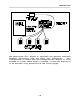
INTRODUCTION ___________________________________________________________________ Figure 1. System Components of Self-contained System 1100. The panel-mount unit (Figure 2) separates the Operator Interface Terminal electronics from the Logic Unit electronics. This configuration is useful when the tonnage monitor display is to be mounted in a panel where depth is limited, or when the display is to be mounted a long distance from the strain gauges.
INTRODUCTION ___________________________________________________________________ Figure 2. System Components for Panel-mount System 1100.
Section 2. 2.1 Operation The Operator Interface The operator interface is the means by which the operator can control the operation of the System 1100. The following features of the Operator Interface will be referred to extensively in this manual and so the operator should be familiar with them. A picture of the Operator Interface is located on the last page of this manual and can be folded out for viewing. 1) Tonnage Displays.
OPERATION ___________________________________________________________________ the low setpoint. The segment representing the measured tonnage relative to the high and low setpoints is lighted each time a new tonnage is displayed. 2.1.1.1 Display of Alarms Alarms are generated when the System 1100 detects that the measured tonnage has exceeded a preset value (high setpoint, reverse setpoint, or machine rating) or in the case of low setpoints, has not exceeded a minimum value.
OPERATION ___________________________________________________________________ of the System 1100. The operator must be in the Main menu and have the keyswitch in the PROG position to access this function. Automatic setup stores the highest and lowest peak tonnage from sixteen successive strokes.
OPERATION ___________________________________________________________________ The LOW LIMIT ON/OFF key is used to switch the low setpoint limits on or off. This functions is accessible only while the keyswitch is in the PROG position. 2.1.2.3 DOWN TIME CODE key The DOWN TIME CODE key is for use with the Link System Tonnage Monitor local area network system and is not used at this time. 2.1.2.
OPERATION ___________________________________________________________________ ERROR 40 - End Of Cycle cam failure, the CLEAR key can be pressed to clear the alarm or error. 2.1.2.7 CONTRAST key The CONTRAST key is used to adjust the contrast of the LCD display. The display can be adjusted brighter or dimmer by holding down the CONTRAST key then pressing the up or down arrow keys respectively.
OPERATION ___________________________________________________________________ interface) provides the operator with information needed to program the System 1100. This is done by displaying a menu (list of choices) and allowing the operator to select one of the menu items. The blinking pointer is called the cursor and is used to identify which item on the list is currently selected.
OPERATION ___________________________________________________________________ (section 2.8.6), the DISPLAY option will appear as the first selection in the Main menu. The Tonnage Display menu, simply called 'DISPLAY' in the Main menu, is used to select which tonnage reading will appear on the tonnage displays. The Tonnage Display menu is shown below.
OPERATION ___________________________________________________________________ SETPTS$PEAK MENU $DW1 (ON) $ $9 DW2 (ON) DW3 (OFF) DW4 (OFF) To view or edit a group of setpoints, select the desired group using the up and down arrow keys, then press the ENTER key. Setpoints for data windows that are turned OFF cannot be viewed or edited until they are turned ON. To turn on or off the use of a data window, first move the keyswitch to the PROG position.
OPERATION ___________________________________________________________________ then enter the new setpoint over the old using the numeric keypad. When finished entering the setpoint, press the ENTER key. The group of setpoints shown above is for the absolute peak tonnage. Data window setpoint groups are indicated as shown below with the data window number appearing in the upper left corner of the setpoints editing screen. DW2 HI-SET LO-SET CH1 11.3 9.3 96 CH2 CH3 CH4 11.3 10.9 11.2 REV-SET (ON) .4 9.2 9.
OPERATION ___________________________________________________________________ the automatic setup function. Manually entering large numbers of setpoints can be tedious, and using automatic setup each time a die is changed gives no indication of what tonnage the die operated at the last time it was used. What is needed is a permanent record of the required tonnage for each die. The System 1100 provides for permanent storage of up to 123 different setups through the Sto/Rcl menu.
OPERATION ___________________________________________________________________ enter the new number over the old using the numeric keypad, then press the ENTER key. 2.5.1.2 ENTER DESC The ENTER DESC screen allows the operator to assign a 16 character description to the current setup. When the ENTER DESC screen is entered, the description of the current setup is displayed as shown below.
OPERATION ___________________________________________________________________ To store the current setup over the setup already in backup memory press the YES key, otherwise press the NO key or the EXIT key. Figure 4. Storing a Setup. At the conclusion of a successful job storage operation, the screen below will be displayed. JOB STORAGE DONE. PRESS EXIT. NOTE: Although setups are stored in the System 1100 the operator is encouraged to keep written records of stored setups.
OPERATION ___________________________________________________________________ 2.5.2.2 ENTER JOB# The ENTER JOB# screen allows the operator to directly enter the number of job to recall. The ENTER JOB# screen is shown below. ENTER JOB NUMBER TO RECALL: ______ The six digit job number is entered by the operator using the numeric keypad. When the operator presses the ENTER key after keying in the job number, the System 1100 searches the backup memory for the requested job and recalls it if it is found.
OPERATION ___________________________________________________________________ Figure 5. 2.5.3 Recalling a Setup. REMOVE The Remove menu allows the user to erase stored job setups from backup memory. The Remove menu is shown below. REMOVE$ENTER JOB# $ MENU $SELECT JOB $9 2.5.3.1 ENTER JOB# The ENTER JOB# screen allows the operator to directly enter the number of the job to remove from backup memory. The ENTER JOB# screen is shown below.
OPERATION ___________________________________________________________________ numeric keypad. When the operator presses the ENTER key the System 1100 searches backup memory for the requested job and erases it if it is found. If the requested job is not found a message indicating so will be displayed. 2.5.3.2 SELECT JOB The SELECT JOB screen allows the user to search through a list of all jobs stored in backup memory and select a job for removing.
OPERATION ___________________________________________________________________ zeroing threshold. The most accurate counts can be obtained when the System 1100 is used with the optional zeroing cam (sections 2.8.5 and 3.5.2). The Counters menu is shown below. CNTRS $PART MENU $BATCH $ $9 QUALITY M.R. ALARM HIGH ALARM LOW ALARM REV. ALARM STROKE 2.6.1 PART, BATCH, and QUALITY COUNTERS The Part, Batch, and Quality counters have presettable limits.
OPERATION ___________________________________________________________________ BATCH CNT: 0012934 (ON) LIMIT: 0123000 While the keyswitch is in the PROG position, the counter limit will flash, indicating that it can be changed. This is done by entering the new limit over the old using the numeric keypad, and then pressing the ENTER key. The counter can be turned on or off while in PROG mode by pressing the ON or OFF keys respectively.
OPERATION ___________________________________________________________________ ENTER ACCESS CODE: ____ The access code is entered by using the numeric keypad, then pressing the ENTER key. If the correct access code is entered, the screen below will then appear. CLEAR COUNTER? (YES/NO) Pressing the NO or EXIT keys will leave the alarm counter value in tact, while pressing the YES key will reset the alarm counter to zero. The alarm counter screen below is shown after the counter has been cleared.
OPERATION ___________________________________________________________________ The Errors menu provides the operator with the capability to view a list of the currently active errors. Error codes are provided with a short plain English explanation of error. An example list of errors is shown below. ERROR 05 - Channel 1 above threshold.9 ERROR 01 - Channel 1 will not zero. ERROR 40 - End Of Cycle cam failure. ERROR 48 - Chan 1 high set too high.
OPERATION ___________________________________________________________________ CONFIG$CAL-CHECK $ MENU $MACH RATING$9 MACH NUMBER THRESHOLD CAM ZERO DATA WINDOW AUTO SETUP MACH SPEED TOPSTOP TMR DECIMAL PT. ALARM CLR MEMORY CLR STATIC-CAL 2.8.1 CAL-CHECK The CAL-CHECK option is used to view the System 1100 calibration numbers. When the operator selects the CAL-CHECK option from the Config menu the screen below will appear and the calibration numbers for each channel will appear in the tonnage displays.
OPERATION ___________________________________________________________________ When the operator selects the MACH RATING option from the Config menu the machine rating screen will appear. An example machine rating screen for a 100 ton machine is shown below. MACHINE RATING: 100.0 A decimal point will automatically appear if the decimal point has been turned on (section 2.8.10). For machines with capacities of less than 500 tons, the decimal point should be turned on.
OPERATION ___________________________________________________________________ threshold will be set at 5% of channel rating. However, on some machines clutch and brake engagement can cause forces in the machine frame greater than this threshold, resulting in nuisance tonnage readings. For this reason the threshold can be adjusted up to 10% in the THRESHOLD screen as shown below.
OPERATION ___________________________________________________________________ The DATA WINDOW screen is shown below. DATA WINDOWS: OFF (ON/OFF TO CHANGE) While the keyswitch is in the PROG position the ON or OFF indicator will flash, indicating that it can be changed. To enable or disable the use of the data windows, press the ON or OFF keys respectively. 2.8.7 AUTO SETUP The AUTO SETUP option in the Config menu allows the operator to set the automatic setup tolerance.
OPERATION ___________________________________________________________________ flash, indicating that it can be changed. The operator can adjust the speed range from 'OVER 600 SPM' to '0-60 SPM' using the up and down arrow keys respectively. Correct setting the machine speed is necessary for the proper operation of the System 1100. Note! For machines running over 500 strokes per minute a zeroing cam should be installed (section 3.5.2). 2.8.
OPERATION ___________________________________________________________________ While the keyswitch is in the PROG position the on/off indicator will flash, indicating that it can be changed. The operator can turn the decimal point on or off by pressing the ON or OFF keys respectively. When the decimal point has been turned on, a decimal point will automatically appear in all setpoint programming screens and the machine rating screen. 2.8.
OPERATION ___________________________________________________________________ 1100 detects that the current setup has inadvertently been corrupted, ERROR 45 (Current job setup corrupt) will result. Two options are available for correcting this situation, the operator can recall a previously stored setup, or can erase the current setup using the MEMORY CLR function.
Section 3. 3.1 Theory of Operation General Load bearing structural members of machines are elastic bodies -stretching, compressing, bending, and/or twisting depending on applied forces. Externally applied forces or moments (torsion) applied to a solid body cause internal stresses (forces per unit area) in that body, resulting in dimensional changes of the body. Such force induced dimensional changes are referred to as strain, and are expressed as changes in length per unit length.
THEORY OF OPERATION ___________________________________________________________________ machine structural members can indicate the force applied by the machine (machine load) as well as the load distribution to structural members in production processes. 3.2 Measurement of Load System 1100 Tonnage Monitors use strain gauge transducers (strain links) mounted to appropriate load bearing structural members of power presses and other machines to measure load.
THEORY OF OPERATION ___________________________________________________________________ monitor total machine tonnage. This monitoring method, however, does not determine load distribution to the two sides of the machine frame due to off center die forces.
THEORY OF OPERATION ___________________________________________________________________ straight side machines, or, in certain applications, on the multiple connections between crankshaft and slide on machines that develop slide motion mechanically. Under these conditions of geometric symmetry, a central machine load should be divided equally to each strain link. Each channel of a two channel tonnage monitor should read 1/2 and each channel of a four channel unit should read 1/4 of a central load.
THEORY OF OPERATION ___________________________________________________________________ Figure 7. The peak tonnage on the left side of the press was 60 tons at time t1. The peak tonnage on the right side of the press was 60 tons at time t2. But the peak total tonnage never exceeded 100 tons. Thus, the correct readings on the tonnage monitor display are 60 tons on the left channel, 60 tons on the right channel, and 100 tons for the total peak tonnage. 3.
THEORY OF OPERATION ___________________________________________________________________ transducers when no load forces are being developed in the machine, and may cause a small variation in displayed tonnage from stroke to stroke for each channel as harmonic strain is added to load strain. It should be noted, however, that the effects of harmonic vibration are generally reduced when the machine actually exerts force in the production process.
THEORY OF OPERATION ___________________________________________________________________ Figure 9. Structural Ringing. The positive going signal is generated by machine frame stretch as the tooling builds up force on the material. The signal increases until the tooling breaks through the partly sheared material, suddenly releasing the machine load to zero.
THEORY OF OPERATION ___________________________________________________________________ Although stress and strain at a bearing structural member is transmitted to that location, loading can induce signals that exerted by tooling.
THEORY OF OPERATION ___________________________________________________________________ distinguished from the strains induced by machine loads and be compensated if tonnage monitors are to provide accurate reading. The temperature induced strains are sensed by tonnage monitor strain links and will shift the "zero" signal (baseline) level from which strains induced by loads are measured unless automatic zeroing of the baseline is provided. 3.5.
THEORY OF OPERATION ___________________________________________________________________ Figure 10. Without the delay time, the tonnage display would be updated three times in a single stroke, retaining only the last (40 ton) peak for a time long enough to be read. Each time the signal goes above the threshold the timer is reset. The threshold level to which a signal has to rise to turn off the automatic zero circuit is about 5% of rated channel tonnage.
THEORY OF OPERATION ___________________________________________________________________ 3.5.2 Automatic Zeroing by Position The second method of automatic zeroing provided on a System 1100 Tonnage Monitor is zeroing by position (cam zeroing). A cam switch or limit switch adjusted to be closed when the machine ram or slide is in a region where no force is generated by tooling "tells" the automatic zero circuit when no load is on the machine, allowing the circuit to be activated.
THEORY OF OPERATION ___________________________________________________________________ Figure 11. Use of a Data Window. The tonnage verses time graph in Figure 10A is for a two station die. The first station stamps a logo onto the part (absolute peak) and the second station cuts out the part (local peak). Since the absolute peak tonnage is created by the coining of the logo, the local peak is not checked using a normal peak tonnage monitor.
THEORY OF OPERATION ___________________________________________________________________ all three types of setpoints (high, low, and reverse) this yields a total of 60 setpoints (5 x 4 x 3 = 60), which is a lot of setpoints to key in by hand! The System 1100 Auto Setup function makes entering these setpoints unnecessary, by automatically calculating and storing all of these setpoints.
Section 4. 4.1 Applications Information Selection of Automatic Zeroing Method As explained in the Section 3 of this manual, two methods of automatic zeroing are possible with a System 1100 Tonnage Monitor. The rate of change method of automatic zeroing requires less hardware (no cam switch or limit switch) and less installation wiring and is excellent for most non-geared mechanical power presses, hydraulic presses, and similar machines.
APPLICATIONS INFORMATION ___________________________________________________________________ Figure 12. "C" Frame Machine. The preferred mounting locations are near the middle of the front of the "C" frame. The forces that occur at the front of the machine frame are tensile forces. The compression forces that occur at the "acceptable" locations at the rear of the "C" frame can be accompanied by nonlinear buckling (bending) on thin web sideframes of some machines.
APPLICATIONS INFORMATION ___________________________________________________________________ mounting the strain links on uprights. On solid frame straight side machines, the uprights are also the best strain link locations. Mounting strain links on each upright gives load distribution to each upright as well as total load. This method helps indicate optimum tooling location to minimize load and machine deflection.
APPLICATIONS INFORMATION ___________________________________________________________________ Figure 13. Straight Side Machine. Stay away from corners of uprights as strain link mounting locations. The best locations on the upright for strain links on machines of tie rod construction are generally on the centerline of the tie rod. Avoid any mounting locations where uprights have internal reinforcements or other change of section.
APPLICATIONS INFORMATION ___________________________________________________________________ Figure 14.
APPLICATIONS INFORMATION ___________________________________________________________________ On solid frame straight side machines, the preferred strain link mounting location is inside the "windows" under the ends of the crankshaft. A strain link should be mounted on the inside face of each column forming the "windows" as shown in Figure 14. Figure 15.
APPLICATIONS INFORMATION ___________________________________________________________________ 4.2.3 Overdrive Double Action Presses Overdrive double action presses have an inner and an outer slide that are driven by connections from crankshafts located in the crown (top) of the press structure.
APPLICATIONS INFORMATION ___________________________________________________________________ Figure 16. Overdriven Double Action Press. If both inner and outer slide tonnage readings are desired, the most accurate measurement is obtained by using strain links on each connection to the outer slide as inputs to one System 1100 Tonnage Monitor, and strain links on each connection to the inner slide as inputs to a second System 1100 Tonnage Monitor. This is illustrated in Figure 15. 4.2.
APPLICATIONS INFORMATION ___________________________________________________________________ tonnage of the inner and outer slide. 4.2.5 High Speed Machines The fast response of the System 1100 peak hold circuits and the total logic cycle time make it possible to monitor tonnage on machines that run continuously at speeds in excess of 2000 strokes per minute (spm).
Section 5. 5.1 Installation Mounting the Enclosure System 1100 Tonnage Monitors are available in two mounting configurations, the self-contained unit, and the panel mount unit. The self-contained unit (Figure 1, page 1-3) houses all System 1100 electronics in one enclosure. Mounting dimensions for the selfcontained unit enclosure are shown in Figure 16. The panel-mount unit (Figure 2, page 1-4) separates the Operator Interface Terminal (OIT) electronics from the Logic Unit electronics.
INSTALLATION ___________________________________________________________________ Figure 17. System 1100 Mounting Dimensions.
INSTALLATION ___________________________________________________________________ Figure 18. System 1100 Remote OIT Mounting Dimensions.
INSTALLATION ___________________________________________________________________ 5.2 Mounting the Strain Links Strain links may be bolted directly to the machine or bolted to intermediate pads welded or adhered to the machine. 5.2.1 Direct Machine Mounting 1) Select the desired mounting locations for the strain links (section 4.2). 2) Remove paint, oil, grease, etc., to obtain a bare metal surface slightly larger than the LST-1000 strain link.
INSTALLATION ___________________________________________________________________ fixture. Note! Do not attempt to locate and drill mounting holes without using the drill fixture. The hole pattern must be precise. 6) Deburr the mounting holes and wipe the mounting area with a clean rag. 7) Mount the strain link as shown in Figure 19. Make certain that the washers provided with the strain link kit are placed over the strain links. Torque the 1/4 x 28 bolts to 150 in-lbs.
INSTALLATION ___________________________________________________________________ 4) Assemble the intermediate pads to the alignment/clamping fixture using the 1/4 x 28 bolts provided, as shown in Figure 20. 5) Hold the alignment/clamping fixture firmly on the mounting area in the direction of tension or compression of the structural member or, alternatively, drill a 5/8 inch deep hole through the center hole of the alignment/clamping Figure 22. LST-1000 Weld fixture, tap for 1/4 x 28 Pads.
INSTALLATION ___________________________________________________________________ pad strain link kit thoroughly. 4) Apply an even coat intermediate pads. 1/16" deep on the bottom of the 5) Clamp the alignment/intermediate pad assembly firmly to the mounting area for at least 24 hours. The press must not be operated during the curing of the epoxy.
INSTALLATION ___________________________________________________________________ 5.4 Electrical Connections 5.4.1 Connecting the Strain Links 1) Pull the strain link cables through the conduit from strain link locations to the System 1100 enclosure (to the Logic Unit for panel-mount versions of the System 1100). 2) Cut excess cable lengths off, leaving about 12 inches of length between the entrance of the cable into the enclosure and the end of the cable.
INSTALLATION ___________________________________________________________________ to the Channel 2 terminals. For a four channel System 1100, connect the strain link designated to be CHANNEL 1 to the Channel 1 terminals, and the strain links designated to be connected to channels 2, 3, and 4, respectively to the Channel 2, 3, and 4 terminals. 5.4.
INSTALLATION ___________________________________________________________________ switch contact can be connected to the machine for grounding. 2) If an ungrounded machine control system is present, run a wire from the second side of the cam switch back to the GND terminal adjacent to the EOC terminal on the Logic board. 3) Adjust the zeroing cam switch as shown in Figure 23.
INSTALLATION ___________________________________________________________________ from 115VAC or higher voltage conductor. 5.4.5 Connecting an Optional Remote Reset A remote reset pushbutton can be wired into the System 1100 allowing alarms and errors to be reset from a remote location. To install the remote reset button, connect one side of a normally open pushbutton to the RST terminal on the System 1100 Logic board.
INSTALLATION ___________________________________________________________________ clutch mechanism, the point in the stroke where the overload occurs, and the machine speed determine whether the machine can stop quickly enough after an overload is sensed to avoid the peak overload. One consequence of connecting the System 1100 into the emergency stop circuit can be sticking the machine on bottom when an overload occurs.
INSTALLATION ___________________________________________________________________ Figure 26. System 1100 Logic Unit Electrical Connections.
Section 6. Calibration Calibration of a System 1100 Tonnage Monitor consists of achieving a known load on the machine and adjusting the installed monitor so that the known load is displayed by the monitor. The known load used during calibration should be at least 50% of rated machine load and preferably 100% of rated machine load.
CALIBRATION ___________________________________________________________________ located under the machine slide. Where multiple load cells or jacks are employed for calibration, they should be located in a geometrically symmetrical pattern with respect to the center of the machine slide. The preferred procedure is to place a single load cell or jack directly under each connection to the slide from crankshaft, hydraulic cylinder, etc., on overdriven machines.
CALIBRATION ___________________________________________________________________ check that the strain links are wired correctly into the Channel cards and refer to error code charts in this manual. 3) Before calibration can proceed, the proper Machine Rating, Machine Speed, and Decimal Point settings must be programmed in the Configuration menu of the System 1100. If these parameters have already been programmed, verify their proper setting in Configuration menu (sections 2.8.2, 2.8.8 and 2.8.10).
CALIBRATION ___________________________________________________________________ position and turn off power to the machine. Place the load cell(s) to be used for calibration into position in the machine. Load cell(s) of similar capacity and dimension are preferably centered under each drive connection (pitman, cylinder rod, etc.) to the slide or ram of the machine. Also place any parallels or similar thickness plates on or under the load cells necessary to reduce the gap between slide and bolster (etc.
CALIBRATION ___________________________________________________________________ The relationship of which load cell is connected to which channel is important. Load cells must be shimmed to carry equal loads in a subsequent step of this calibration procedure and the force generated by the machine on the load cell is indicated by the channel of the "portable" System 1100 to which the load cell is connected.
CALIBRATION ___________________________________________________________________ supply module is located on the left side of the enclosure. (Note: The GND connection is important to avert possible electrical shock.
CALIBRATION ___________________________________________________________________ 1100 is used as a "portable" calibration unit. Follow the procedures in section 2.4.1 of this manual to set the low setpoints for each channel of the "portable" System 1100 to zero (0). 13) Set the calibration number for each channel of the "portable" System 1100 unit to the specified value labelled on the load cell connected as an input to the respective channel.
CALIBRATION ___________________________________________________________________ 16) If a single load cell is used for calibration, continue to single stroke the machine and adjust shut height or other bottom of stroke adjustment until the rated capacity of the load cell or the machine, whichever is less, is reached on the CHANNEL of the "portable" unit to which the load cell is input.
CALIBRATION ___________________________________________________________________ the CLEAR key must be pushed to obtain further readings. Vibratory motion in the machine often introduces stroke to stroke variations of one or two percent in the load cell tonnage readings. When this happens it is impractical to try to refine the load on the machine any closer than within one or two percent of rated tonnage.
CALIBRATION ___________________________________________________________________ be kept in files. If the calibration numbers displayed on the tonnage displays for a particular channel vary, take the median value of the numbers displayed as the calibration number. 19) Press the EXIT key to end CAL-CHECK mode. 20) Remove the load cells and associated "stack" elements from the machine and disconnect the cables from the load cells and the "portable" System 1100 unit. Calibration is complete. 6.
CALIBRATION ___________________________________________________________________ number of each channel will then appear in each tonnage display. For a two channel System 1100 unit, adjust the GAIN ADJUST potentiometer for CHANNEL 1 (left strain gauge) until the number 400 appears on the channel 1 tonnage display. Adjust the GAIN ADJUST potentiometer for CHANNEL 2 (right strain gauge) until the number 400 appears on the channel 2 tonnage display.
CALIBRATION ___________________________________________________________________ For a four channel System 1100 unit, rotate the GAIN ADJUST for CHANNEL 1 until the number appearing on the channel 1 tonnage display reads within ±1% of one-fourth (1/4) of the sum of the tonnages exerted by the jack(s). Repeat this procedure for channels 2, 3, and 4. 12) Release the pressure of the jack(s) and remove the jack(s) and associated stack materials from the machine. 13) Press the EXIT key to end STATIC-CAL mode.
Section 7. Zero Circuit Checkout After Calibration If the "rate of change" automatic zeroing method (no cam switch used for zeroing) is used, it is necessary to verify that strains induced in the machine frame due to mechanical noise, such as engagement of clutches or brakes or gear "slap" do not exceed the factory set zeroing threshold of 5% of rated channel tonnage. 1) Select a die from the group of dies used in the machine with one of the heaviest upper die weights.
ZERO CIRCUIT CHECKOUT ))))))))))))))))))))))))))))))))))))))))))))))))))))))))))))))))))) zeroing threshold. 4) Proceed to step 4 of this procedure. Mechanical noise due to deceleration forces as the machine slide stops at the end of a stroke that exceed the 5% zeroing threshold will displace the tonnage display readings obtained due to tooling forces at the bottom of the stroke.
Section 8. Unbalanced Loads and Scale Factor Most machines that use force in production processes are designed for distributed central loads at rated tonnage and lesser noncentral (eccentric) loads. However, some forging presses and other machines are designed to permit operation at full tonnage with either central loads or, within specified limits of offset from center, non-central loads.
UNBALANCED LOADS AND SCALE FACTOR ___________________________________________________________________ may prevent the machine from operating with acceptable non-central loads. This can be rectified by a simple procedure involving changing both the machine rating number (scale factor) and the channel calibration numbers.
UNBALANCED LOADS AND SCALE FACTOR ___________________________________________________________________ ORIGINAL MACHINE RATING C'N1 = C'N2 = C'N3 C'N4 ------------------------NEW MACHINE RATING * CN1 ORIGINAL MACHINE RATING ------------------------NEW MACHINE RATING * CN2 = ORIGINAL MACHINE RATING ------------------------NEW MACHINE RATING * CN3 = ORIGINAL MACHINE RATING ------------------------NEW MACHINE RATING * CN4 and where C'N1, C'N2, C'N3, C'N4, are the new calibration numbers to
UNBALANCED LOADS AND SCALE FACTOR ___________________________________________________________________ 0.635 Reprogram the machine rating number from the original 100 ton value programmed during calibration to 112 tons. Next calculate the new calibration numbers required to remain calibrated with the new machine rating number. These are: C'N1 100 = ----- * 144 . 129 112 100 C'N2 = ----- * 148 . 132 112 Round off calibration numbers calculated as above to the nearest whole number.
UNBALANCED LOADS AND SCALE FACTOR ___________________________________________________________________ C'N2 = ----- * 532 . 416 128 100 C'N3 = ----- * 535 . 418 128 C'N4 100 = ----- * 524 . 409 128 Adjust the calibration numbers to the new values, i.e., 411 for channel 1, 416 for channel 2, 418 for channel 3, and 409 for channel 4.
Section 9. Using System 1100 Tonnage Monitors There are several possible levels of utilization of System 1100 Tonnage Monitors in everyday production operations. In addition, there are several special purpose and diagnostic uses that a System 1100 can perform. This section of the manual gives suggestions for using the System 1100. The information provided should be considered as guidance.
USING SYSTEM 1100 TONNAGE MONITORS ___________________________________________________________________ increasing pressure on hydraulic machines. 2) If no alarms are tripped on the System 1100 during trial strokes, including several trial strokes after the final adjustment that produces a satisfactory part, the machine may be turned over to production.
USING SYSTEM 1100 TONNAGE MONITORS ___________________________________________________________________ cannot be produced without overloading the machine. 9.1.2 Sample Operator Instructions 1) Each time power is first turned on to the machine, observe that the System 1100 tonnage displays go to zero (0) before attempting to cycle the machine. 2) Observe that a reading appears on the tonnage displays after the first machine stroke that produced a part.
USING SYSTEM 1100 TONNAGE MONITORS ___________________________________________________________________ 1) Initially determine and record the optimum location and minimum required tonnage for each set of tools used in a machine.
USING SYSTEM 1100 TONNAGE MONITORS ___________________________________________________________________ die location and tonnage, the location and required tonnage is ideally recorded and attached to the die set as a reference for future setup and for determining die wear. The high and low setpoint limits should then be determined for each channel. The high setpoints for each channel should be set far enough above each channel tonnage that normal variations in tonnage don't trip the high setpoint alarms.
USING SYSTEM 1100 TONNAGE MONITORS ___________________________________________________________________ around the measured tonnage. The Auto Setup tolerance can be increased and the Auto Setup function executed again if nuisance stops due to normal variations in production tonnage occur. Once established, the initial setpoint tonnages for each channel of the System 1100 should be recorded on the label that contains initial optimum location and tonnage records for reference in future setups.
USING SYSTEM 1100 TONNAGE MONITORS ___________________________________________________________________ to allow this variation or, alternatively, the operator may reset setpoints during operation after equilibrium is reached as indicated by readings on the System 1100 tonnage displays. 9.2.
USING SYSTEM 1100 TONNAGE MONITORS ___________________________________________________________________ distribution can be use of different shims or parallels on dies or different location of shims or parallels from setup to setup. If, when the TOTAL tonnage is adjusted to the initial reference value recorded on the die, a correct part can't be made, adjust the tonnage slowly upward till a correct part is produced.
USING SYSTEM 1100 TONNAGE MONITORS ___________________________________________________________________ caused the alarm cleared before pushing the CLEAR key on the System 1100 and proceeding with production.
USING SYSTEM 1100 TONNAGE MONITORS ___________________________________________________________________ tonnage near the least value that produces a correct part. 3) After correct setup is finished, use the Auto Setup function to calculate and set all high, low, reverse tonnage setpoint limits to a preset tolerance around the measured tonnage. The Auto Setup tolerance can be increased and the Auto Setup function executed again if nuisance stops due to normal variations in production tonnage occur. 9.3.
USING SYSTEM 1100 TONNAGE MONITORS ___________________________________________________________________ the machine tooling stretches (strains) the tie rod by an amount proportional to load and releases the compressive forces in the uprights proportionally to load.
USING SYSTEM 1100 TONNAGE MONITORS ___________________________________________________________________ Snapthrough forces associated with blanking or piercing action can be displayed on the System 1100 by pressing the TONNAGE FORWARD/REVERSE key to select reverse tonnage. Reverse tonnage is indicated by a minus sign on the tonnage displays.
Section 10. 10.1 Error Codes Error Listing System 1100 errors are indicated by the STOP CIRCUIT indicator light flashing. The codes and descriptions for any active errors can be displayed using the ERRORS option in the main menu (section 2.7). Errors are cleared by pressing the CLEAR key. Depending on the System 1100 configuration, the keyswitch may have to be in the PROG position to clear errors. The following is a listing of error codes generated by the System 1100 Tonnage Monitor, software version 1.
ERROR CODES ___________________________________________________________________ Error No. Message / Action strain link on the same dual channel card. Now swap the strain link connections, plugging the strain link in error into the adjacent strain link's socket and vise versa. Turn on power to the System 1100. If the error code moves to the swapped channel, then the strain link or strain link wiring is causing the error and should be checked.
ERROR CODES ___________________________________________________________________ Error No. Message / Action 2) 031 If running at speeds greater than 500 SPM a zeroing cam switch should be installed. Supply Voltage too low. When the operator attempts to change information stored in the non-volatile memory of the System 1100 the power supply voltage is first checked for the proper level.
ERROR CODES ___________________________________________________________________ Error No. 035 Message / Action Internal Error. 1) 036 Call Factory. Notify Link Systems of this error. Failure of Automatic Setup. This error results when the sixteen stroke automatic setup procedure is completed properly but a hardware failure prevents the new setpoints from being transferred into the non-volatile memory. 1) 037 Press the CLEAR key to clear the error. Auto Setup time-out.
ERROR CODES ___________________________________________________________________ Error No. 041 Message / Action Failure of Communications. This error indicates that the Operator Interface Terminal cannot communicate with the Logic Unit. 042 1) Check the communication cable connecting terminals A, B, and C of the Operator Interface terminal to the Logic Unit. 2) Check that the power supply connectors on the Operator Interface Terminal and the Logic Unit are properly connected. Internal Error.
ERROR CODES ___________________________________________________________________ Error No. Message / Action This error results volatile memory. 1) from a failure of the non- If the setup has been previously stored in backup memory, go to the Sto/Rcl menu and recall the setup. If the setup is not present in backup memory, use the CLR MEMORY option in the Config menu to erase the current job setup. Follow the steps outlined in section 2.8.12. 046 Config data is corrupt.
ERROR CODES ___________________________________________________________________ Error No. 048 049 050 051 Message / Action Channel Channel Channel Channel 1 2 3 4 high high high high setpoint setpoint setpoint setpoint too too too too high. high. high. high. The Peak tonnage high setpoint of the channel indicated by the error code is set to a value greater than 125% of the channel rating. 052 053 054 055 1) Check the MACH RATING setting in the Config menu for correctness.
ERROR CODES ___________________________________________________________________ Error No. Message / Action than 125% of the channel rating. 060 061 062 063 Channel Channel Channel Channel 1 2 3 4 high high high high setpoint setpoint setpoint setpoint < < < < low low low low setpoint. setpoint. setpoint. setpoint. The Peak tonnage high setpoint of the channel indicated by the error code is set to a value less than the low setpoint.
ERROR CODES ___________________________________________________________________ Error No. Message / Action 2) 072 073 074 075 Adjust the indicated setpoint to a setting less than 125% of the channel rating. Data Data Data Data window window window window 1, 1, 1, 1, channel channel channel channel 1 2 3 4 reverse reverse reverse reverse setpoint setpoint setpoint setpoint too too too too high. high. high. high.
ERROR CODES ___________________________________________________________________ Error No. 084 085 086 087 Message / Action 1) Check the MACH RATING setting in the Config menu for correctness. 2) Adjust the indicated setpoint to a setting less than 125% of the channel rating. Data Data Data Data window window window window 2, 2, 2, 2, channel channel channel channel 1 2 3 4 low low low low setpoint setpoint setpoint setpoint too too too too high. high. high. high.
ERROR CODES ___________________________________________________________________ Error No. Message / Action The Data window 2 high setpoint of the channel indicated by the error code is set to a value less than the low setpoint. 1) 096 097 098 099 Adjust the high or low setpoint so that the high setpoint is greater than the low setpoint.
ERROR CODES ___________________________________________________________________ Error No. 107 Message / Action Data window 3, channel 4 reverse setpoint too high. The Data window 3 reverse setpoint of the channel indicated by the error code is set to a value greater than 125% of the channel rating. 108 109 110 111 1) Check the MACH RATING setting in the Config menu for correctness. 2) Adjust the indicated setpoint to a setting less than 125% of the channel rating.
ERROR CODES ___________________________________________________________________ Error No. 117 118 119 Message / Action Data window 4, channel 2 low setpoint too high. Data window 4, channel 3 low setpoint too high. Data window 4, channel 4 low setpoint too high. The Data window 4 low setpoint of the channel indicated by the error code is set to a value greater than 125% of the channel rating. 120 121 122 123 1) Check the MACH RATING setting in the Config menu for correctness.
ERROR CODES ___________________________________________________________________ Error No. Message / Action setpoint is greater than the low setpoint.