Configuration and Operations Manual (Color OIT) Link Electric & Safety Control Company 444 McNally Drive Nashville, TN 37211 PH: (615) 833-4168 FAX: (615) 834-1984 OmniLink 5000 PLC Interface
Table of Contents Section 1 Introduction . . . . . . . . . . . . . . . . . . . . . . . . . . . . . . . . . . . . . . . . . . . . . . . . . . . . . . . 1.1 Section 2 Parameter Entry and Access Control . . . . . . . . . . . . . . . . . . . . . . . . . . . . . . . . . . . . Section 2.1 Parameter Entry . . . . . . . . . . . . . . . . . . . . . . . . . . . . . . . . . . . . . . . . . . . . . . . . . Section 2.1.1 Numeric Entries . . . . . . . . . . . . . . . . . . . . . . . . . . . . . . . . . . . . . . . . .
Section 5.7.3 Section 5.7.4 Section 5.7.5 Section 5.7.6 Section 5.7.7 Section 5.7.11 Section 5.7.12 Section 5.7.13 Section 5.7.14 Section 5.7.15 Section 5.7.16 Section 5.7.17 Section 5.7.18 Section 5.7.19 Section 5.7.20 Section 5.7.21 Section 5.7.22 Section 5.7.24 Section 5.7.25 Section 5.7.26 Section 5.7.27 Section 5.7.28 Section 5.7.29 Section 5.7.30 Section 5.7.35 Section 5.7.36 Section 5.7.37 Section 5.7.38 Section 5.7.39 Section 5.7.40 Section 5.7.41 Section 5.7.42 Section 5.7.43 Section 5.7.
Section 5.7.61 Parameter 061 - Order Count . . . . . . . . . . . . . . . . . . . . . . . . . . . . . . . . . . . Section 5.7.62 Parameter 062 - Batch Count . . . . . . . . . . . . . . . . . . . . . . . . . . . . . . . . . . . Section 5.7.63 Parameter 063 - Quality Count . . . . . . . . . . . . . . . . . . . . . . . . . . . . . . . . . Section 5.7.64 Parameter 064 - Counter 4 Count . . . . . . . . . . . . . . . . . . . . . . . . . . . . . . . Section 5.7.65 Parameter 065 - Counter 5 Count . . . . . . . . . .
iv
Section 1 Introduction The Link PLC interface is intended to allow communications between Link equipment and generic external devices (primarily PLCs, but other devices could be used - the term PLC will be used in this manual to refer to both) . Features include: Up to 4 user defined screens can be configured. Each screen can be given a title and a softkey name for navigation. Each screen can have up to 16 user defined parameters.
June 5, 2000 Man ual Rev 1 .0 1.
Section 2 Parameter Entry and Access Control Section 2.1 Parameter Entry Throughout the OmniLink control, a fairly standard form of data entry is employed. When data entry is allowed, an “editing cursor” will appear on the screen. This cursor can typically be moved from parameter to parameter on the screen with the up, down, left, and right arrow keys. The topmost softkey is used to select the parameter for editing and can change description depending on the parameter selected. Section 2.1.
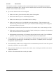
Figure 2.1: Example Text Entry c) The fist character of the text is highlighted with the text cursor. The CURSOR LEFT and CURSOR RIGHT softkeys will move this cursor. d) Use the left and right arrow keys to point to the letter desired in the letter box next to the text being edited. This box will just appear above or just below the text to be edited depending on where it is in the screen. Hit the SELECT LETTER softkey to place that letter at the text cursor.
Section 2.2 Access Control The OmniLink control has several parameters or operations that have limited access. The ability to perform certain operations or change certain parameters should typically be restricted to authorized personnel. The OmniLink control provides several means to limit access to these parameters or operations. These parameters and operations are called restricted items. The OmniLink control employs combinations of two different means to limit access to restricted items.
The example above can be taken one additional step, if two press operators are given different user names and different passwords. One operator can be assigned the ability to change tonnage monitor limits in addition to the ability to reset tonnage monitor faults, while the other operator is not assigned the ability to change the tonnage monitor limits. Section 2.2.3 Password Only Mode The “Password Only” mode allows for sixteen users. Each user can be assigned access to some or all of the restricted items.
stroking will be prohibited until the switch is returned to the RUN position. When operating in the Key Only mode the key switch is the only means available to access the restricted items. All restricted items are accessible when the RUN/PROG key switch is switched to the PROG position. When operating in the “Key or Password” mode, the key switch is one of the means available to access the restricted items. All restricted items are accessible when the RUN/PROG key switch is switched to the PROG position.
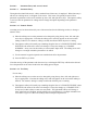
Figure 2.2 only User Number One, User Number Two, and User Number Five have access to this restricted parameter. The system may have several more users, but the three users listed on the screen are the only users that have access to change a High Peak Limit. The user must use the arrow keys to position the cursor on his user name. After placing the cursor on the correct name, the user must press the SELECT softkey. The SELECT softkey must be pressed even if there is only one user name displayed.
Section 3 Configuration Before the PLC Interface can be configured, it must be enabled in the Auxiliary Communications Setup screen. To get to this screen: a) Press the “CONFIGURE” softkey in the Press Control Screen. The configuration access code will have to be entered to gain access to this screen. b) Press the “OPERATOR TERMINAL” softkey. c) Press the “AUXILIARY COMM SETUP” softkey. d) The screen should now look similar to that of Figure 3.
not appear, make sure it is not currently configured on another port. f) Once “PLC Interface” is selected to run on the port, press the “CONFIGURE COMM TASK” Figure 3.2: Example PLC Main Configuration Screen softkey and the screen of Figure 3.2 should appear. Section 3.1 The Main PLC Interface Configuration Screen The main PLC Interface configuration screen (shown in Figure 3.2) contains settings that apply to the PLC Interface as a whole. Individual PLC screens are configured separately.
there is a problem with the communications link. Send Dec Pt: Choices are “Yes” and “No”. If the setting is “Yes” then a decimal point will be sent to the PLC for parameters that have one. If “No” then the number will be sent without a decimal point. For instance, if parameter 1 is configured with 6 digits and 3 decimal places, it might look like “123.456" on the screen. If “Send Dec Pt” is “Yes” then the PLC Interface would send “123.456" to the PLC.
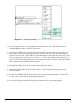
without requiring a separate display. To do this, the PLC sends a command to the OmniLink OIT that indicates which status line is being addressed (there are up to 4 per screen) and the message number to Figure 3.3: Example “Screen Status Message Configuration” screen display (See section 5 for details on the message format). The messages themselves are configured in this screen. Figure 3.3 shows an example “Screen Status Message Configuration” screen.
previous group of messages. Likewise, use the “NEXT PAGE” softkey to see the next group of messages. Section 3.3 NOTE: Parameter Status Message Configuration Parameter status messages are not a required part of the PLC Interface. If status and/or error messages from the PLC are not going to be displayed on the OmniLink operator terminal, then this section may be skipped. The PLC interface allows the PLC to display specific status and/or error messages for each configured parameter, if desired.
Status Message Each message can be up to 15 characters long. This is the message that will be displayed on the screen when the PLC selects this message number. To change a message description, place the editing cursor in the message to be changed and press the “CHANGE TEXT” softkey. Enter the new message using the text entry system described in Section 2.
The features of this screen are: Parameter Name: Up to 20 characters can be entered as the name of each parameter. This name will be displayed on the PLC user screen. ND: The number of digits for this parameter. Valid values are 1 to 8. DP: The number of decimal places for this parameter. Valid values are 0 to 7 but must also be at least 1 less than the number of digits. A 0 for this value means no decimal point will be used. Min. Val.: The minimum value for this parameter.
Notice that some screen formatting is possible by leaving “gaps” between parameters. In the example of Figure 3.5, a parameter is skipped between “Clamp 4 Status” and “Clamp Pressure”. This will leave a blank line between these two parameters on the PLC operation screen. Press the “SET SCREEN SOFTKEYS” softkey to configure softkeys for this PLC screen. See section 3.5 for details. Press the “SET SCREEN STATUS LABELS” softkeys to configure the legends for screen status messages for this screen.
Figure 3.6: Example PLC Softkey Configuration Screen Each PLC action key (“PLC Softkey 2" through “PLC Softkey 6") can be enabled or disabled by selecting “Yes” or “No” for the “Used” parameter. Softkeys that are not used will not be displayed on the PLC operation screen. See Figure 4.1 to see how these keys would look on the PLC operation screen. Section 3.6 NOTE: Screen Status Label Configuration PLC Screen Status Labels are not a required part of the PLC Interface.
Figure 3.7: Example Status Label Configuration Screen The four status lines can be individually enabled or disabled on a line by line basis. If “Line X Used” is “Yes” then the status line will be shown on the PLC operation screen (see “e” on Figure 4.1 to see what this configuration shown in Figure 3.6 would look like on the operation screen) Each status line label can consist of up to 15 characters.
June 5, 2000 Man ual Rev 1 .0 3.
Section 4 Operation The operation screen for the PLC interface is reached in the following manner: a) Press the “ACC” key on the OmniLink 5000 Operator Interface Terminal. This key can be pressed from almost any screen in the control. The Quick Access screen should be displayed. b) Press the “AUXILIARY COMM.” softkey. This should bring up the Auxiliary Communications Status screen. All configured communications interfaces that require operator input will have a status display and softkey on this screen.
“Last Fault” line (“d”). To clear the top stop, the stop condition must be corrected (communications restored etc.) and the “RESET ERROR” softkey must be pressed. Note that this key will only appear when an error condition has been detected. Item “c” The current communications status is displayed here. Note that this is entirely different from a PLC screen or parameter status message. This line shows the state of communications between the OmniLink OIT and the PLC.
Section 5 Communications Protocol This section is for those responsible for programming the PLC or other device that will communicate with the Link PLC Interface . The protocol uses messages that consist of a start of message character, a data field, and an end of message character. Note that all numbers transferred have leading zeros if necessary to fill out the number field. Section 5.1 [LF] [CR] [S] # PLC - Conventions Start of Message Character. Line Feed (decimal 10, hex 0A).
“Standard Numeric” in this document. Values that include decimal points are, by default, sent without the decimal point. For example 123.456 would be sent as 000123456. Decimal points can be sent by setting “Send Decimal Point” to “Yes” in the Main PLC Configuration Screen. 123.456 would then be sent as 000123.456. Section 5.4 Text Value Formats In order to keep the protocol as simple as possible for the PLC to handle, a fixed text format is employed.
Section 5.5.2 User Parameter Command This sends a user defined parameter to the PLC. From Link: [LF]U[PNUM]=[PVAL][CR] where: [PNUM] is a three digit parameter number (with leading zero if necessary). [PVAL] is the value of the parameter. Reply from PLC: return of message. Notes: If the user has user parameters enabled on the Link equipment, then one or more of these commands will be sent on power-up, when a job is recalled, and when the user changes a value.
Section 5.6 Requests From the PLC to Link Equipment The PLC can request certain information from the Link equipment. The commands that do this differ from regular commands in that they cause the Link equipment to not only generate a reply to the PLC, but expect the PLC to echo the reply back. This was done to ensure reliable data transfer. When the Link equipment gets an information request command, it will send the information and expect the command to be echoed back from the PLC for verification.
Section 5.6.2 Request to Change Job Jobs can come from local storage or, if LinkNet is installed, can be downloaded from a host computer. The methods for doing either technique are very similar. Section 5.6.2.1 Load Job From Local Storage From PLC: [LF]SETJOB=#########[CR] where: ######### = nine digit job number with leading zeros if necessary. Reply from Link: Generates Job Number Command (See section 5.5.1).
It can take a relatively long period of time (around 30 seconds) for the reply to come from this request. When the job change request is received, the Link equipment checks to see if the job is valid. If it is, the job is recalled. If the job is not valid, a job number command is still generated but the job number will be unchanged. Therefore, it is a good idea to check the reply to this message to verify the job has been changed as intended. Section 5.6.
[PVAL] will vary depending on the parameter requested. Numeric value will generally be a 9 digit zero padded number. Text values will 40 characters long. See section 5.7 for details. Section 5.7 Machine Parameter Reference Machine parameters allow certain information to be extracted from the Link Equipment. Each parameter has a unique parameter number. The information is requested as outlined in section 5.6.4 Section 5.7.
Meaning: The Day number (1-31) reported from the real time clock on the OmniLink OIT. Section 5.7.4 Parameter 004 - Year Value: Standard Numeric Meaning: The Year number (2000, 2001, etc) reported from the real time clock on the OmniLink OIT. Section 5.7.5 Parameter 005 - Hour Value: Standard Numeric Meaning: The Hour number (0-23) reported from the real time clock on the OmniLink OIT. Section 5.7.
Meaning: The numeric “current status” code for the “A” side of the Press Control. A zero for this value indicates the press is ready to run. See parameter 082 for a command to get the actual text description of this code. Section 5.7.12 Parameter 012 - Press Control “B” Current Status Code Value: Standard Numeric Meaning: The numeric “current status” code for the “B” side of the Press Control. A zero for this value indicates the press is ready to run.
Section 5.7.16 Parameter 016 - Crankshaft Angle Value: Standard Numeric Meaning: The angle of the press crankshaft in .01 degrees. Note that if “Send Decimal Point” is “No”, then the PLC must assume a decimal position of two. For example: 30 degrees would be sent as 3000 45.6 degrees would be sent at 4560 359 degrees would be sent as 35900 etc. Due to serial port speed limitations, this value should not be considered a real-time angle value.
Section 5.7.19 Parameter 19 - Press Stroking Mode Value: Standard Numeric Meaning: Numeric code for the stroking mode of the press. The following codes apply: 1 2 3 4 5 6 7 8 = = = = = = = = Inch Single Stroke Auto Single Stroke Continuous Timed Inch Setup/Stop Time Test Continuous on Demand Maintained Continuous Section 5.7.20 Parameter 020 - Mode Select Key Flag Value: Standard Numeric Meaning: Non-Zero if Mode Select Key is active.
Value: Standard Numeric Meaning: Non-Zero if Clutch is engaged. This basically tells the PLC when the press is actually stroking. Section 5.7.24 Parameter 024 - Crankshaft Direction of Rotation Value: Standard Numeric Meaning: 0 for forward rotation. Non-Zero for reverse rotation. Section 5.7.25 Parameter 025 - Stop Time Limit (Top) Value: Standard Numeric Meaning: The stopping time limit of the press in milliseconds for stops at the top of the stroke. See Press Control Manual for more information.
Value: Standard Numeric Meaning: The stopping time of the press in milliseconds the last time it stopped. Section 5.7.29 Parameter 029 - Last Stop Position Value: Standard Numeric Meaning: 0 = Did not stop at top. 1 = Stopped at top. Section 5.7.30 Parameter 030 - Last Start Time Value: Standard Numeric Meaning: The starting time in milliseconds the last time the clutch was engaged. Section 5.7.
Standard Numeric, 1 decimal place Meaning: Same as parameter 35 Section 5.7.37 Parameter 037 - Peak Forward Tonnage (Channel 3) Value: Standard Numeric, 1 decimal place Meaning: Same as parameter 35 Section 5.7.38 Parameter 038 - Peak Forward Tonnage (Channel 4) Value: Standard Numeric, 1 decimal place Meaning: Same as parameter 35 Section 5.7.39 Parameter 039 - Peak Forward Tonnage (Total) Value: Standard Numeric, 1 decimal place Meaning: Same as parameter 35 Section 5.7.
7.3 tons will be sent as 73 12 tons will be sent as 120 Note that this is true even if the tonnage monitor itself does not show a decimal point on its screen. Section 5.7.41 Parameter 041 - Peak Reverse Tonnage (Channel 2) Value: Standard Numeric, 1 decimal place Meaning: Same as parameter 40 Section 5.7.42 Parameter 042 - Peak Reverse Tonnage (Channel 3) Value: Standard Numeric, 1 decimal place Meaning: Same as parameter 40 Section 5.7.
0 2 4 6 8 10 12 14 = = = = = = = = OK Channel Error TOTAL Alarm Peak Degree Error DW 1 Setpoint Error DW 3 Setpoint Error UNUSED UNUSED Section 5.7.46 1 3 5 7 9 11 13 15 = = = = = = = = Tonnage Alarm Vref Shorted Machine Rating Error Peak Setpoint Error DW 2 Setpoint Error DW 4 Setpoint Error UNUSED Bypassed Parameter 046 - Tonnage Monitor Channel 2 Status Value: Standard Numeric Meaning: Same as parameter 45 Section 5.7.
The number of channels configured for the tonnage monitor. Section 5.7.51 Parameter 051 - Tonnage Monitor Machine Rating Value: Standard Numeric Meaning: The machine rating of the press as configured in the tonnage monitor. Section 5.7.52 Parameter 052 - Tonnage Monitor Reverse Limits ON Flag Value: Standard Numeric Meaning: 0 = Reverse limits are OFF 1 = Reverse Limits are ON Section 5.7.
Value: Standard Numeric Meaning: 0 = 1 = 2 = 3 = 4 = All Conditions OK Communication Failure Bypassed Error Condition Exists - See Channel Status Option is Not Installed Section 5.7.56 Parameter 056 - Auto-Setup Module Enabled Flag Value: Standard Numeric Meaning: 0 = Auto-Setup NOT enabled 1 = Auto-Setup enabled Section 5.7.57 Parameter 057 - Auto-Setup Slide Adjust Switch Flag Value: Standard Numeric Meaning: The slide adjust switch position as reported by the auto-setup module.
Section 5.7.59 Parameter 059 - Stroke Count Value: Standard Numeric Meaning: The value of the OmniLink Stroke Counter. Section 5.7.60 Parameter 060 - Stroke Count Value: Standard Numeric Meaning: The value of the OmniLink Scrap Counter. Section 5.7.61 Parameter 061 - Order Count Value: Standard Numeric Meaning: The value of the OmniLink Order Counter. Section 5.7.62 Parameter 062 - Batch Count Value: Standard Numeric Meaning: The value of the OmniLink Batch Counter. Section 5.7.
Standard Numeric Meaning: The value of the OmniLink Auxiliary Counter 4. Section 5.7.65 Parameter 065 - Counter 5 Count Value: Standard Numeric Meaning: The value of the OmniLink Auxiliary Counter 5. Section 5.7.66 Parameter 066 - Counter 6 Count Value: Standard Numeric Meaning: The value of the OmniLink Auxiliary Counter 6. Section 5.7.67 Parameter 067 - Counter 7 Count Value: Standard Numeric Meaning: The value of the OmniLink Auxiliary Counter 7. Section 5.7.
Value: Standard Numeric Meaning: The value of the OmniLink Auxiliary Counter 7. Section 5.7.70 Parameter 070 - Counter 10 Count Value: Standard Numeric Meaning: The value of the OmniLink Auxiliary Counter 10. Section 5.7.71 Parameter 071 - Order Counter Limit Value: Standard Numeric Meaning: The Limit of the Order Counter. Section 5.7.72 Parameter 072 - Batch Counter Limit Value: Standard Numeric Meaning: The Limit of the Batch Counter. Section 5.7.
Section 5.7.74 Parameter 074 - Counter 4 Limit Value: Standard Numeric Meaning: The Limit of Auxiliary Counter 4. Section 5.7.75 Parameter 075 - Counter 5 Limit Value: Standard Numeric Meaning: The Limit of Auxiliary Counter 5. Section 5.7.76 Parameter 076 - Counter 6 Limit Value: Standard Numeric Meaning: The Limit of Auxiliary Counter 6. Section 5.7.77 Parameter 077 - Counter 7 Limit Value: Standard Numeric Meaning: The Limit of Auxiliary Counter 7. Section 5.7.
Section 5.7.79 Parameter 079 - Counter 9 Limit Value: Standard Numeric Meaning: The Limit of Auxiliary Counter 9. Section 5.7.80 Parameter 080 - Counter 10 Limit Value: Standard Numeric Meaning: The Limit of Auxiliary Counter 10. Section 5.7.81 Parameter 081 - Job Description Value: Standard Text Meaning: The Job Description of currently loaded job. Section 5.7.
June 5, 2000 Man ual Rev 1 .0 5.
Section 5.8 Sending Status Message Codes The OmniLink Color OIT can be configured to display status messages for PLC operation screens and for individual parameters as outlined in section 3. Section 5.8.1 Screen Status Command Format There are 4 possible PLC operation screens, each with up to 4 status messages. To select a status message for display, the line number and status message number must be supplied to the OmniLink OIT.
The format to select a parameter status message is: From PLC: [LF]VS[PNUM]=[MNUM][CR] where: [PNUM] is the two digit parameter number (with leading zero if necessary) . [MNUM] is the message number that is to be set for the line. Reply From Link: [LF]VSA[PNUM]=[MNUM][CR] where: [PNUM] is the two digit parameter number (with leading zero if necessary) . [MNUM] is the message number that was set for the line.