
User guide


August 30, 2002 Manual Version 1.0
4.7
Section 4.2.1 Machine Parameters Menu
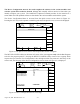
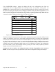
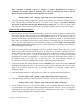
Pressing the Machine Parameters softkey in the Main Configuration menu accesses the Machine
Parameters menu, shown in Figure 4.6. This menu is where you will begin the configuration process.
Figure 4.6 Machine Parameters Configuration Menu
Note that some numeric settings may already be programmed when you receive the unit. These
settings were made during the checkout of your unit at the factory and must be reprogrammed as
you configure the system based on the specific characteristics of your press.
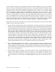
Section 4.2.1.1 Configuring the Encoder (Resolver) Type
The first step after you have initially installed the OmniLink II system will be to select the
Encoder Type setting on the Machine Parameters menu. An encoder is provided with each
OmniLink II Press Automation Control to be driven in a one-to-one ratio by the crankshaft of the press
to supply crankshaft angular position information to the system. The angular position display in the
upper left corner of the screen displays the angle provided by the encoder.
Link offers two different encoders with the OmniLink II Press Automation Control. The standard
encoder is the 2500 Resolver. An optional 5000 Resolver is also offered that combines a resolver and an
optical encoder in the same enclosure to allow cross checking of the angular position information. You
must determine which resolver you ordered with your system and set either “2500” or “5000” as the
Encoder Type setting, the first menu item in the Machine Parameters Menu. This setting will be selected
(highlighted) when the screen first appears. When the Encoder Type setting is selected, pressing the
Change Setting softkey will toggle the setting between “2500” and “5000”. If you have a 2500 resolver
and the setting already appears as 2500 in the highlighted area, you don’t need to push the Change
Setting softkey.
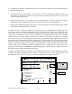
Section 4.2.1.2 Setting Top of Stroke Angle
After setting the Encoder Type, look at the Top of Stroke Angle setting, the third menu item from the
SOFTKEYS
WHEN
ENCODER
OFFSET IS
SELECTED
SOFTKEYS
WHEN
NUMERIC
SETTINGS
SELECTED
CHANGE
NUMBER
EXIT
TO P
STOP
MID
STOP
RESET
FA UL T
SET
ZERO
CHA NGE
NUMBER
EXIT
TOP
STOP
MID
STOP
RESET
FAULT
Stroke
Mo de
Dr i ve
Speed
Stroke
Speed
SPM
SPM
0
0
Orde r
Counter
SYSTEM STATUS
Counter OFF
8
0
OK
Machine
Para ms
CHANGE
SETTING
EXIT
Encoder Type :
Enco de r Offs et :
Top of Stroke Angle :
Minimum Press Speed :
Loss of Mot ion Time :
Use Mode Input :
Clutch Engagement Time Limit :
Brake Monitor Top Stop Limit :
Brake Monitor Mid Stroke Stop Limit :
Brake Monitor Actual Stop Time :
Clutch Actual Engagement Time :
2500
0
0
2
20
No
20
20 0
20 0
15 0
95
0
o
o
msecs
msecs
msecs
msecs
msecs
msecs
SPM
(TOP)
TO P
STOP
MID
STOP
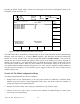
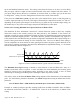
NOTE! The last two items are not settings
and a value canno t be entered f or
them. They are actu al measured times for stopping and clutch engagement
th at appear each time the press starts and stops. They are used to determine
the proper brake m onitor and clutch engagement time limits in the
configuration process as described in the co nfiguration sections for brak e
monitor and clutch engagement ti me .
RESET
FAULT
Appears on ly w hen st op limit or clutch engagement time limit
is exceeded
SPE ED
CONFIG