
User guide


August 30, 2002 Manual Version 1.0
2.20
Section 2.3.8 Optional Solid State Relay Outputs
The OmniLink II Press Automation Control provides an optional solid state relay module. It can be
supplied with a combination of AC or DC solid state relays specified by the customer. If the module is
provided, the relays provide the following functions:
• R1 and R2 – Module programmable limit switches 1 and 2. Simple on at an angle off at an angle
PLS’s for limited applications.
• R3 – Provides an output to drive an external light that indicates die protection is bypassed.
• R4 – Provides an output to drive an external light to indicate that a downtime code has been entered
when the optional LinkNet information system software is used.
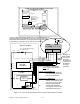
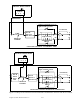
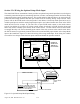
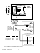
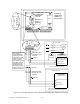
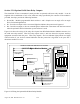
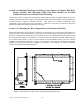
Figure 2.18 shows the wiring of the relay drive inputs from R/D-Brake Monitor Module connector 2 to
the solid state relay module. Wire PLS relay outputs (relay 1 and 2)as desired to sequence auxiliary
equipment associated with the press. Wire relay outputs 3 and 4 to indicator lights placed in a highly
visible location if you wish an external indication that die protection is bypassed or the press has a
downtime condition or event.
Figure 2.18 Wiring the Optional Solid State Relay Module
Transformer
Fus e
Outp ut
Relay s
Micro pr ocess or 2
Micro pr ocess or 1
Mi cr o pr o c. 1
Prog. Memory
R 1 2 3 4 5 6 7 8 9 1 0 1 1 12 1 3
CO N7
SHLD
GND
CA NH
CANL
Can Termination
Switch
CO N1
CO N2
1 2 3 4 5 6 7 8
L1 L2 G ND
CO N5
1 2 3 4
CO N4
1 2 3 4 5
CO N8
R/D
IC
Analog Input/Output
Board Option
802-5 R/D-Brake Monitor Module
CON9
1 2 3 4 5
CON2
1 2 3 4 5 6 7 8
OPTIONAL 802-5
SS RELAY MODULE
12VDC
INSIDE OF OPERATOR TERMINAL ENCLOSURE
R1 R2 R3 R4
SOLID S TATE RELAY
DRIVE SIGNALS
SO LID S TATE RELAY
OUTPUTS. USE BLUE
WIRE FOR DC AND
RED WIRE FOR AC
RELAY OUTPUTS .