
User guide


August 30, 2002 Manual Version 1.0
2.19
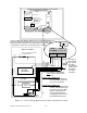
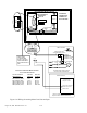
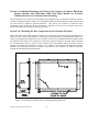
Figure 2.17 Wiring to Display and Set SPM Through OmniLink II Operator Terminal
EDDY CURRENT
COUPLING COIL
DC MOTOR DRIVE OR
AC ADJUSTABLE
FREQUENCY DRIVE
PRESS CONTROL
DRIVE GROUND
ANALOG 0-10V SPM OUTPUT
FOR D C MOT OR DR IV E OR AC A D J U ST AB LE
FREQUENCY DR IVE VARI ABLE SPEED PRES SE S
Transformer
Fuse
Output
Relays
Microprocessor 1
Micr oproc. 1
Prog. Memory
R1 2 3 4 5 6 7 8 9 10 11 12 13
CON7
SHLD
GND
CANH
CANL
Can Termination
Sw itch
CON1
CON2
1 2 3 4 5 6 7 8 L1 L2 GN D
CON5
1 2 3 4
CON4
1 2 3 4 5
CON8
R/D
IC
Analog Input/Output
802-5 R/D-Brake Monitor Module
INSIDE OF
OPERATOR
TERMINAL
ENCLOSURE
1 2 3 4 5
CON8
SPM IN
ISO GND
ISO GND
SPM OUT
%LOAD
1M
MAIN MOTOR
1OL
1OL
1OL
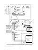
PRESS CONTROL
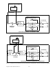
FOR EDDY CURRENT DRIVE PRESSES
21
1234
1234
SWITCH
Board Option
OPEN
Throw switch 1 to
closed position if eddy
current tach generator
is referenced to ground
on eddy current drive &
for DC or AC motor
drives with analog voltage
speed outputs. Switch to
open position for eddy
current tach generator
that is input to a bridge
rectifier (rarely the case)
on the eddy current drive.
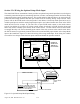
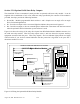
EDDY CURRENT DRIVE
DRIVE GROUND
DRIVE SPM FEEDBACK
ISOLATED
INPUTS &
OUTPUT
DRIVE SPM INPUT
DRIVE SPM INPUT
3
TACH
GENERATOR
SHIELDED CABLE
IN LOW VOLTAGE
CONDUIT
SHIELD
No Connection
No Connection
SHIELD
SHIELDED CABLE
IN LOW VOLTAGE
CONDUIT