
User guide


August 30, 2002 Manual Version 1.0
7.13
a
b
c
d
b
a
e
Stroke
Mode
Drive
Speed
Stroke
Speed
SPM
SPM
0
0
Order
Counter
SYSTEM STATUS
Counter OFF
Limit
Switch
CHANGE
CHANNEL
SETTING
EXIT
0
0
Program/Run Switch
TOP
Production
NEXT
PAGE
180
0
270 90
Ch Mode Description Status State
CONFIGURE
RESET
FAULT
1
2
3
4
5
6
7
8
Normal
Timed Off
Toggle
Normal
Normal
Always Off
Always Off
Always Off
Feed Initiate
Air Blow Off
Parts Bin Select
Pilot Pin Release
Die Spray Lube
OK
OK
OK
OK
OK
OK
OK
OK
On
Off
Off
Off
Off
Off
Off
Off
Channel 1 Details
System Status: OK
Module Status: OK
Channel
Status
Ok
On Angle:
Off Angle:
270°
10°
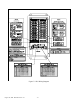
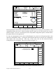
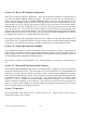
Figure 7.6 Referenced Die Protection Screen
a) Channel Settings These are the parameters that define the logic type, window on and off angles,
description, and type of stop to be issued on fault conditions. See Section
7.7.1.
b) Selected Channel
Information
Specific information about the programmable limit switch channel that is
currently selected. See Section 7.7.1
c) Reset After a fault has been detected, a stop will be sent to the press control. Before
production can resume, the system must be reset to clear the stop. See
Section 7.7.2
d) Configure Configuration allows the user to select the manner that the system can be reset
and the use of Speed advance Outputs. See Section 7.6.
e) Status
Information
The status of the viewed channel, individual module, and the entire
programmable limit switch system. See Section 7.7.3