
User guide

August 30, 2002 Manual Version 1.0
6.24
Stroke
Mode
Drive
Speed
Stroke
Speed
SPM
SPM
0
0
Order
Counter
SYSTEM STATUS
Counter OFF
Die
Protection
CHANGE
SETTING
EXIT
0
0
Program/Run Switch
TOP
Production
BYPASS
ON/OFF
NEXT
PAGE
180
0
270 90
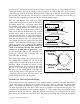
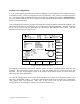
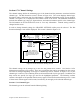
Ch Channel Type Description Status State
CONFIGURE BYPASS 20
STROKES
CHANNEL
DIAGS
RESET
ERRORS
1
2
3
4
5
6
7
8
Static
Static
1 Part Detector Edge
In Position
Cyclic
Cyclic
Cyclic
Cyclic
Stock Buckle
End of Stock
Part Detector
Feed Complete
Left Front Stripper
Right Front Stripper
Left Rear Stripper
Right Rear Stripper
OK
OK
OK
OK
OK
OK
OK
OK
Off
On
Off
Off
Off
Off
Off
Off
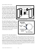
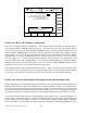
Module 1, Channel 5 Details
System Status: OK
Module Status: OK
Channel
Status
Ok
Input Type:
Stop Type:
Bypassed:
Delay Time:
Delay Strokes:
Window On:
Window Off:
Normally Off
Top Stop
No
0 msecs
0 strokes
154º
213º
BYPASS
SETUP
a
b
c
d
c
e
f
a
c
g
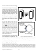
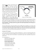
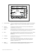
Figure 6.22 Referenced Die Protection Screen
a) Channel Settings These are the parameters that define the logic type, window on and off angles,
description, and type of stop to be issued on fault conditions. See Section
6.71.
b) Channel
Diagnostics
The diagnostic information aids the user in setup of the channels and in
troubleshooting. See Section 6.72.
c) Bypass When monitoring of an individual channel or the entire system is not required,
the individual channel or system must be bypassed. See Section 6.73.
d) Reset After a fault has been detected, a stop will be sent to the press control. Before
production can resume, the system must be reset to clear the stop. See
Section 6.74.
e) Configure Configuration allows the user to select the manner that the system can be reset
and bypassed. See Section 6.6.
f) Stop Types When a channel fault has been detected, a stop will be sent to the press
control. There are three different stop types; cycle stop, top stop, and
intellistop. See Section 6.7.1.4.
g) Status
Information
The status of the view channel, individual module, and entire digital die
protection and process monitoring system. See Section 6.76.