
User guide

August 30, 2002 Manual Version 1.0
2.2
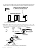
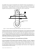
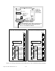
It is also convenient to run the 115VAC power along with the high-speed serial bus cable to each
module(s) enclosure in the same flexible liquid tight conduit with ground, as indicated in Figure 2.2.
Figure 2.2 Serial Bus Connections
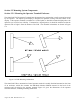
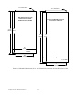
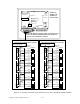
3. Dual connector plugs are used for each optional module shown in Figure 2.2 for both the high-
speed serial bus and 115VAC power connection to the module. This allows both the serial bus and
power connections to be strung from module to module as shown in Figure 2.3.
Figure 2.3 Dual Connector Plugs for Modules for Serial Bus and Power
USE THE SWITCH ON THE OPTION INSTALLED
AT THE FAR END OF THE CABLE FROM THE
OPERATOR TERMINAL TO TERMINATE THE
SERIAL BUS CABLE.
OPERATOR
TERMINAL
ENCLOSURE
O
P
T
I
O
N
1
O
P
T
I
O
N
5
O
P
T
I
O
N
3
O
P
T
I
O
N
2
O
P
T
I
O
N
4
SERIAL BUS CABLE AND POWER FOR
MODULES RUN IN SAME CONDUIT
G
N
D
L
1
L
2
115 VAC FROM
LAST MODULE
115 VAC CO NNEC T OR PLUG
FOR THIS MODULE
115 VAC TO N EXT
MODULE
16 GA RE D, WH ITE ,
GREEN WIRES
16 GA RE D, WH I TE ,
GREEN WIRES
PLUGS INTO MODULE
CONNECTOR HEADER
FOR THIS MODULE
SERIAL BUS CABLE
FROM LAST MODULE
SERIAL BUS CONNECTOR
PLUG FOR THIS MODULE
SERIAL BUS CABLE
TO NEXT MODULE
SHIELD MUST BE
CONNECTED TO PLUG
PLUGS INTO MODULE
CONNECTOR HEADER
FOR THIS MODULE
Cable Wire Color Connector
Terminal
White CANL
Orange CANH
Blue GND
Bare Shield