OPERATING MANUAL Version 1.
Section 1 Introduction..................................................................................1.1 Section 1.1 Base System...................................................................................................................................................... 1.1 Section 1.1.1 Base System Standard Features................................................................................................................. 1.1 Section 1.1.2 Base System Optional Features......................
Section 4.2.1.8 Setting Brake Monitor Top Stop and Brake Monitor Mid Stroke Stop Limits ................................4.13 Section 4.2.2 Speed/Load Configuration Menu Settings...............................................................................................4.14 Section 4.2.2.1 Setting Speed Mode .........................................................................................................................4.15 Section 4.2.2.
Section 5.6.2 Recall Setup ............................................................................................................................................ 5.20 Section 5.6.3 Erase Setup.............................................................................................................................................. 5.21 August 30, 2002 Manual Version 1.
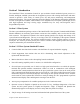
Section 1 Introduction The OmniLink II Press Automation Control for part revolution clutch mechanical power presses is a flexible, intelligent, modular system that can be applied to presses with existing clutch brake and motor controls to provide a wide variety of control; press, die, and process monitoring; and management information functions. The system integrates setting and display of all functions through the OmniLink II Color LCD Operator Terminal, which includes a 9.
Section 1.1.2 Base System Optional Features • An optional analog input/output card allows stroking speed to be adjusted and displayed on the operator terminal even when not stroking for variable speed presses. It also allows motor load current to be displayed. • Serial Feed Interface for most available electronic roll feeds.
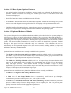
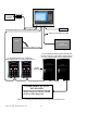
Section 1.3 System Overview Figure 1.1 shows the base package hardware components for the OmniLink II Press Automation Control. Crank or Eccentric Shaft RESOLVER OMNILINK II PRESS AUTOMATION CONTROL RESOLVER CABLE Figure 1.1 OmniLink II Press Automation Control Base System Package Figure 1.2 (next page) shows the existing and planned components and features of the system with optional components. August 30, 2002 Manual Version 1.0 1.
RESOLVER CRANK OR ECCENTRIC SHAFT OMNILINK II PRESS AUTOMATION CONTROL RESOLVER CABLE LINKNET HIGH SPEED SERAIL BUS CABLE (3 WIRES AND DRAIN) SERIAL PLC INTERFACE CABLE FEED PROGRAMMABLE LOGIC CONTROLLER SERIAL FEED INTERFACE CABLE UP TO 32 PROGRAMMABLE LIMIT SWITCH AND 32 LOGIC OUTPUTS - 8 OR 16 RELAYSPER MODULE 16 LOGIC & MONITORING INPUTS PER MODULE UP TO 80 DIE PROTECTION & PROCESS MONITORING INPUTS -- 8 OR 16 PER MODULE MODEL MODEL 5120 MODEL 5100-5 LINK DIE PROTECTION & PROCESS MONITOR MODUL
Section 2 Installation Section 2.1 Preliminary Installation Considerations 1. Before you begin to install your OmniLink II Press Automation Control, you should read this entire manual carefully. This will help you to understand system functions and plan the installation to save time and the necessity to rework portions of the installation. 2.
It is also convenient to run the 115VAC power along with the high-speed serial bus cable to each module(s) enclosure in the same flexible liquid tight conduit with ground, as indicated in Figure 2.2. USE THE SWITCH ON THE OPTION INSTALLED AT THE FAR END OF THE CABLE FROM THE OPERATOR TERMINAL TO TERMINATE THE SERIAL BUS CABLE. OPERATOR TERMINAL ENCLOSURE SERIAL BUS CABLE AND POWER FOR MODULES RUN IN SAME CONDUIT O P T I O N O P T I O N O P T I O N O P T I O N O P T I O N 1 2 3 4 5 Figure 2.
4. NEVER use any cable other than that supplied by Link Systems for the high-speed serial bus that interconnects the various components of the OmniLink II Press Automation Control. This cable has been chosen to optimize communication speed and distance for the serial bus. Use of other cables may result in communication faults that cause nuisance stops of your press production system. DO NOT splice sections of cable between OmniLink II modules. Use unbroken runs of cable between modules. 5.
Section 2.2 Mounting System Components Section 2.2.1 Mounting the Operator Terminal Enclosure The OmniLink II LCD Operator Terminal must be mounted in a position that is easily seen and accessed by the operator. The liquid crystal display is designed for optimum viewing from the bottom of the display. If the operator terminal is mounted in a vertical plane, it should be mounted slightly above the operator's eye level for best visibility.
0.312 (.792) Diameter (4 Places) 11.00 ( 27.74) OmniLink II LCD OPERATOR TERMINAL 0 T OP Driv e Speed Strok e Speed 0 Strok e Mode 0 SP M 0 SP M Order C ount er N Counter OOFF SYS TEM STATUS OK READY TO STROKE MAIN S CREEN 11.65 (29.59) 10.4 (26.
The standard resolver used with the OmniLink II press Automation Control is the 2500 Resolver. A 5000 Resolver can optionally be used with the system. In either case, a spring loaded mounting base, as shown in Figure 2.7, will be supplied with the resolver to maintain chain tension if the resolver is chain and sprocket driven. Mount the resolver on the spring base. Mount the spring base to accommodate alignment of chain and sprockets so that they may be driven by crank or eccentric shaft.
.312 (.7925) 4 Places .312 (.7925) 4 Places 8 OR 16 CHANNEL DIE PROTECTION AND PROCESS MONITOR MODULE ENCLOSURE ENCLOSURE FOR SINGLE PLS/LOGIC MODULE 10.5 11.125 (28.258) (26.67) 13.75 (34.925) 13.3 (33.782) 6.6 (16.76) 4” DEEP 4.25 (10.795) 7 (17.78) 4.75” DEEP 4.75 (12.065) Figure 2.8 Mounting Dimensions for 8 or 16 Channel Die Protection or Single PLS/Logic Units August 30, 2002 Manual Version 1.0 2.
Section 2.3 Wiring System Modules and Components Section 2.3.1 Conduit Runs Wiring between the enclosures for OmniLink II Press Automation Control components should be run in conduit. The use of flexible liquid tight conduit with ground is suggested, but hard conduit can also be used. Figure 2.9 shows some of the typical conduit runs that may be required.
The conduit runs that you will or may need, depending on the options you purchase and features that you wish to use on your OmniLink II, are: • • • • • • • Conduit from resolver to R/D-Brake Monitor Module in OmniLink Operator Terminal enclosure. Conduit for 115VAC connections between OmniLink Operator Terminal and Press Control.
802-5 R/D-Brake Monit or Module Analog Input/Ou tpu t Boa rd O ptio n Micr opr ocessor 2 Tra nsfo rme r Micr opr ocessor 1 INSIDE OF OPERATOR TERMINAL ENCLOSURE Mi cropr oc. 1 P rog. Me mor y O utpu t R elay s R/ D IC C an Ter minatio n Switc h CON8 3 4 5 6 7 8 9 10 1 1 12 13 G ND R1 2 3 4 5 Fus e CON5 CON2 CANL CON1 CON7 SHLD 2 CA NH 1 1 2 3 4 5 6 7 8 CON4 L1 L2 GN D 1 2 3 4 SYSTEM 2500 RESOLVER CABLE CONNECTION TO CON7 OF 802-5 R/D-BRAKE MONITOR MODULE.
802-5 R/D-Brake Monitor Module Analog Inp ut/Ou tpu t Boa rd Optio n Micr opr ocessor 2 Tra nsfo rme r INSIDE OF OPERATOR TERMINAL ENCLOSURE Micr opr ocessor 1 Mi cropr oc. 1 P rog . Me mor y Outpu t R elay s R/ D IC C an Termina tio n Switc h CON8 6 7 8 9 10 11 12 1 3 G ND CON1 CON7 R1 2 3 4 5 CANL 3 4 5 SHLD 2 CA NH 1 CON2 CON5 1 2 3 4 5 6 7 8 L1 L2 GN D 1 Fus e CON4 2 3 4 CON 7 SYSTEM 5000 RESOLVER CABLE CONNECTION TO CON7 OF 802-5 R/D-BRAKE MONITOR MODULE.
Section 2.3.3 Wiring 115VAC Power From Press Control to Operator Terminal Pull red, white and green 16 gauge wires in the 115VAC conduit between the OmniLink II Operator Terminal enclosure and the press control (along with other wiring to be run in this conduit) and connect as shown in Figure 2.13. The control transformer in the press control will preferably be used to supply the 115VAC power for all the components of the OmniLink II Press Automation Control. As shown previously in Figure 2.
INSIDE OF OPERATOR TERMINAL ENCLOSURE 802-5 R/D-Brake Monitor Module Analog Input/Output Board Option Microprocessor 2 Transformer Microprocessor 1 Microproc. 1 P rog. Memory Output Relays R/D IC Can Term inatio n Switch CON8 4 5 R 1 2 3 4 5 6 7 8 9 1 0 1 1 12 1 3 CON1 GND CON7 CANL 3 S HLD 2 CA NH 1 Fuse CON5 CON2 1 2 3 4 5 6 7 8 CON4 L1 L2 G ND 1 2 3 4 Contacts on R/D- Brake Monitor Module used to provide both immediate stop and top stop signals from OmniLink to press control.
Section 2.3.4 Wiring the Valve Voltage Circuit The OmniLink II Press Automation Control brake monitor and motion detector functions require a signal from the press clutch/brake control that indicates when the press strokes and stops stroking. This signal is derived from the voltage across the dual air valve solenoid (in some cases a hydraulic valve may be used) that controls stroking.
R/D-Brake Monitor Module 1 CONN4 2 3 4 Jumpers inside this box if no light curtain is present E.S. Buttons 1RCSA 15 X X X X 36 Slot 26 501-8A or 501-20 Card 76 20 6 60 46 Light Curtain REMOVE JUMPER 2RCSA LINK SS501 CONTROL- STANDARD CARDS R/D-Brake Monitor Module CONN4 1 2 3 4 Jumpers inside this box if no light curtain is present E.S.
Section 2.3.6 Wiring the Optional Setup Mode Input The OmniLink II Press Automation Control provides an optional setup mode input that is used to bypass certain die protection and process monitoring functions, counters, and tonnage monitor low limits during setup activities that require stroking the press. This avoids nuisance faults that have to be reset on the die protection and tonnage monitor and false part counts based on stroking during setup activities.
Section 2.3.7 Wiring Optional Analog Input/Output Board Circuits Section 2.3.7.1 Wiring to Display Motor Load Current If the optional Analog Input/Output board is specified with the OmniLink II Press Automation Control, and you wish to graphically and numerically display motor load current on the OmniLink II Operator Terminal, refer to Figure 2.16.
802-5 R/D-Brake Monitor Module INSIDE OF OPERATOR TERMINAL ENCLOSURE 4 Analog Input/Output Board Option SWITCH 2 3 3 Microproc. 1 Prog.
802-5 R/D-Brake Monitor Module INSIDE OF OPERATOR TERMINAL ENCLOSURE 4 Analog Input/Output Board Option SWITCH 2 3 3 Microproc. 1 Prog. Memory 1 2 1 CON8 2 3 4 Can Termination Switch 5 CON8 1 2 3 SHLD 9 10 11 12 13 ISO GND SPM OUT 7 8 %LOAD ISO GND S PM IN R1 2 3 4 5 6 GND CON1 CON7 CANL 1 Throw switch 1 to closed position if eddy current tach generator is referenced to ground on eddy current drive & for DC or AC motor drives with analog voltage speed outputs.
Section 2.3.8 Optional Solid State Relay Outputs The OmniLink II Press Automation Control provides an optional solid state relay module. It can be supplied with a combination of AC or DC solid state relays specified by the customer. If the module is provided, the relays provide the following functions: • • • R1 and R2 – Module programmable limit switches 1 and 2. Simple on at an angle off at an angle PLS’s for limited applications.
Section 2.4 Additional Mounting and Wiring if the Operator Terminal, R/D-Brake Monitor Module, and (Optionally) Solid State Relay Module are Provided Without Enclosure for Customer Panel Mounting The OmniLink II Press Automation Control base system package may be purchased without the operator terminal, R/D-Brake Monitor module, and (optionally) Solid State Relay Module already mounted and pre-wired inside an Operator Terminal enclosure.
CON 7 R1 2 3 4 5 6 7 8 9 10 11 12 13 CON 1 CON 2 1 2 3 4 5 6 7 8 CON 5 CON 4 1 2 3 4 Figure 2.20 R/D-Brake-Monitor Module with Mounting Bracket for Mounting in Customer’s Enclosure Section 2.4.2 Wiring the Base Components in the Customer Enclosure The only wiring not shown in previous figures where base system components were supplied in an enclosure is the wiring between R/D-Brake Monitor Module and Operator Terminal.
in separate documents sent in addition to this manual when these options are purchased with your system. Section 2.6 Wiring the Parallel Port for Messages from Auxiliary Equipment (Optional) The OmniLink II Press Automation Control makes provision to wire inputs to its parallel port on the back of the operator terminal from auxiliary equipment intelligent controllers so that diagnostic messages from auxiliary equipment can be displayed on the brake monitor screen of the operator terminal.
Section 3 Operator Terminal Basics Section 3.1 OmniLink II Press Automation Control LCD Operator Terminal The OmniLink II Operator Terminal features a 9.2” diagonal color TFT liquid crystal display (LCD) with high brightness and large viewing angle, a keypad, and a Program/Run keyswitch.
stopped within +/- 5 degrees of bottom dead center, the box will be yellow with the letters “BOT”. For speeds greater than sixty strokes per minute, two rotating arrows will appear in the circle. These rotating arrows indicate crankshaft motion. The remainder of the top portion of the screen displays four user selectable items. These four user selectable items can be chosen by the user from a list in the User Configuration menus . The currently available items are: 1.
choose to configure the system to allow certain commonly used settings and actions to be done in Run Mode. Fine adjustment of some angle settings can also be done in Run Mode.
Section 3.5 CHG Key This changes the display language from English to Spanish. Depressing the CHG key again will return the display language to English. Section 3.6 Arrow keys The Up, Down, Left, and Right arrow keys are used to select settings that may be entered or changed on any display menu where settings are provided. They are also used to select one item from a list of items to enter as a setting.
keys on the keypad and pressing the ENT (Enter) key after you have changed the number to the desired value. The CLR key will clear the present number being entered, and the entry process is aborted by pressing the EXIT softkey or one of the arrow keys. The numeric data will not change from the previous value if the entry process is aborted. This process is illustrated in Figure 3.2, which shows a portion of the Counter programming screen. Selected (Highlighted) Number to Change.
0 T OP Drive Speed Stroke Speed 0 S troke Mode Die Prot.
0 TOP Drive Speed Stroke Speed 0 Stroke Mode 0 SPM 0 SPM Order Counter OFF Counter SYSTEM STATUS OK Die Protection Channel Names NUM 1 2 3 4 5 6 7 8 9 10 11 12 13 14 15 16 17 18 19 20 Die Pro.
This illustration is for the Die Protection Channel Names Screen that will be present if one or more optional Die Protection and Process Monitoring Modules is used with the system. But, the same pop up text entry box will appear on any other screen that allows entry of alphanumeric names or text. Letters are entered by using the left and right arrow keys to position the letter pointer under the desired letter and then pressing the SELECT LETTER softkey.
means available to access Program Mode. All settings and actions for the system are accessible to anyone when the Program/Run key switch is switched to the PROG position. If Code Only access mode is selected by the user in the configuration mode, the Program/Run key will only be used to provide access (in conjunction with the User Configuration Code) to the User Configuration Mode. The Program/Run key will not access Program Mode. Programming Mode is accessed by code (password) only.
0 TO P Drive Spe ed Stroke Spe ed Description Stock Buckle 0 Stroke Mode Ch Channel T ype 1 S tat ic 2 Not Used 3 1 Part Dete ctor Edge 4 In Position 5 Cyclic 6 Cyclic 7 Cyclic 8 Cyclic Input Type: Stop Typ e: Bypassed: Delay Time: Delay St rok es: Window On : Window Of f: Channel OK Status Or der Counter OFF Counter SYS TEM STATUS OK 0 SPM 0 SPM Status OK OK OK OK OK OK OK OK Par t Ou t Die Cam Retr act ed Str ipp er Le ft Front Str ipp er Right Fron t Str ipp er Le ft Rear Str ipp er Right Rear Mo
Section 3.9.3 Code (Password) System Operation If any of the access modes to Program Mode that use a code is chosen in the User Configuration Mode, code access to the system to perform setting(s) or action(s) is a log on operation that requires a user to enter his name (or classification) and a code associated with the user name. The system will also ask for a name and code whenever softkeys that allow access to settings or actions restricted to Program Mode, such as reset or bypass, are pressed.
module) and a group of eight channels for that module. One module may have up to 16 channels. The PREVIOUS PAGE softkey will appear above the NEXT PAGE softkey only after the NEXT PAGE softkey is used to select a group of eight other than those shown on the first page. Use the Up/Down arrow keys to move the cursor (highlight) to a channel whose settings are to be changed. In the figure above, channel 5 on die protection module 1 is selected. Press the upper right softkey (CHANNEL SETTINGS).
0 TOP 0 Stroke Mode Drive Speed Stroke Speed Die Prot. Channel Configuration Channel Type: Cyclic Descript Input T Select a User Name Stop T Bypass John Delay Ti Jane Delay Stro Ed Window Sam Window Joe 0 SPM 0 SPM Module: 1 Order Counter OFF Counter SYSTEM STATUS OK Channel: 5 DP Chan DP Chan Config Settings SELECT Help Sets the type of Logic to apply to the channel Press Select after using Use Up/Down arrow keys to highlight your user name in list Ted 0 Cyclic - Norm.
0 T OP 0 S troke Mode Drive Speed Stroke Speed Die Prot.
new 60 second cycle will be started. The number of strokes that are entered is the number of press strokes after the last keystroke that will be allowed before the system automatically logs out the user. For example, if the automatic timeout is set to 10 strokes, the user will be logged out when the press completes ten strokes after the last keystroke. If the user depresses a key before 10 strokes have been completed, a new 10 stroke cycle will be started. August 30, 2002 Manual Version 1.0 3.
Section 4 Device and Main Configuration Menus After your OmniLink II Press Automation Control is first installed and BEFORE you begin to use the system, you must configure the OmniLink II for and its components for its use on the particular press. The system provides access to two sets of configuration menus that set up the base system for all press operations, the Device Configuration Menu, and the Main Configuration Menu.
The Device Configuration menu is also used to update the software in the various modules used with the system when needed or desired, although this normally will not need to be done when you initially configure your system. The OmniLink II Operator Terminal provides for the insertion of a smart media card with updated software to download to the various modules used with the system. The Device Configuration Menu is accessed from the Quick Access screen shown in Figure 4.1.
The left column of the Device Configuration screen lists hardware modules that can be used with the system. The center column indicates whether the device is used with this particular OmniLink system. The right column is used to indicate information pertaining to device status, such as “detected”, which means the Operator Terminal has established communication with the module. The TOGGLE USED softkey will toggle the “Used” column for the highlighted (selected) device from No to Yes or Yes to No.
Pressing the NEXT PAGE softkey causes the second page of the Device Configuration menu to be displayed, as shown in Figure 4.3.
4. Configuring the Operator Terminal serial ports for any software options, such as serial feed interface and PLC Interface used. 5. Choosing whether certain bypass or reset actions for both standard and optional features are unrestricted, or whether these actions can only be done by persons you have chosen to do so in the security settings of the system. 6.
If the CONFIGURE softkey is pressed, the display will ask for the configuration code. This user configuration code is user programmable and is the highest order user password for the system. An original code is sent from the factory to a person designated when the control is ordered. The user has the option of keeping the original code or changing to another during the initial configuration or at a later time if desired.
Section 4.2.1 Machine Parameters Menu Pressing the Machine Parameters softkey in the Main Configuration menu accesses the Machine Parameters menu, shown in Figure 4.6. This menu is where you will begin the configuration process.
top on the Machine Parameters menu. This setting comes from the factory as 00 since it is most likely that your press will have simple eccentric motion instead of the more complex link drive motion. If your press slide is directly driven by a crankshaft, an eccentric shaft, or eccentric gear you do not need to change the 00 setting. Go to the setting discussed in the next section of this manual.
If the loss of motion time value calculated by the formula is not longer than the time that motion can dip below the Minimum Press Speed, loss of motion faults will result. If these occur, you may increase the time calculated by the formula but, in no case, should this time be increased more than 2.5 times the value calculated by the formula. Section 4.2.1.
Method 1. Slide at Top of Stroke 1. Inch the press to position the crankshaft within +/- 1 degrees of top dead center (00 -- slide at top of stroke). This is important because the system uses the crank angle as its absolute reference and will assume that the crankshaft position is at zero degrees when it calculates the Encoder Offset.
Thus, regardless of whether you have a negative or positive misalignment of encoder to crankshaft, the Encoder Offset to manually enter when you calibrate the resolver with the slide at the top of stroke position is determined by the relation: Encoder Offset = 3600 – Display Angle (with current Encoder Offset setting of 0) 4. Verify that the angle display changes to 00 after you press the Set Zero softkey or manually enter an offset. Manual entry of numbers between 00–90 and 3500–3590 is allowed.
Section 4.2.1.6 Use Mode Input Setting The OmniLink II Press Automation Control provides an input that allows the user to provide an isolated contact to the operator terminal, when this can be derived from the press clutch/brake control, to indicate when the setup mode (usually Inch) is selected. When this input is provided, it allows die protection functions and counters to be bypassed when a setup mode is selected, if desired.
be accommodated so that adjustment on a frequent basis is not necessary. A typical wear margin of 20% is usually sufficient. To determine the number to enter for the Clutch Engagement Time Limit with a 20% wear margin, take the longest time recorded and multiply it by 1.2. For example., if the longest time recorded is 100 milliseconds, enter a value of 120 milliseconds for the Clutch Engagement Time Limit. Section 4.2.1.
3. Take the longest stop time recorded in step 2 and add a 10% to 20% margin for wear and other factors that affect this time to determine the Brake Monitor Top Stop Limit setting. For example, if your longest recorded stopping time is 170 milliseconds, 20% of this value is 34, and a setting of 204 milliseconds for the Brake Monitor Top Stop Limit would allow top stopping time to increase by 34 milliseconds before a brake monitor fault would prevent a successive stroke.
8 Drive Speed Stroke Speed 0 Stroke Mode 0 SPM 0 SPM Order Counter OK Speed/Load Config Speed Mode: Not Used Calibration Parameters Maximum Input SPM : 0 SPM Input Offset : 0 SPM Input Cal # : 0 Percent Load Cal # : 0 Minimum Output SPM : Minimum Output Cal # : Mid Range Output SPM : Mid Range Output Cal # : Maximum Output SPM : Counter OFF SYSTEM STATUS CHANGE SETTING 0 0 0 0 0 ENTER CAL. MODE Speed Parameters Prod.
Use the arrow keys to select your choice of 3 Speed Mode settings; Input Only, Output Without Recall, or Output With Recall. The significance of these settings is: • Input Only. If Input Only is selected, an analog speed input signal must be provided to the Analog Input/Output Board from the variable speed drive as shown in Section 2.3.7.2 of this manual. This will allow display of the selected drive stroking speed, and stroking speed of the press can be displayed even when the press is not stroking.
6. Select the CONTINUOUS stroking mode on the press stroking selector and initiate press stroking. 7. The actual stroking speed will be shown at the top of the OmniLink Operator Terminal display beside Stroke Speed as long as the press is stroking. This Stroke Speed will be used to calibrate the Motor (Drive Speed). If the Input SPM Cal # parameter is set to 0, the Motor Speed (Drive Speed) at the bottom of the screen will be 0. Calibration numbers between 0 and 4095 can be entered for the Input SPM Cal #.
2. Return to the Speed/Load Configuration menu and set Speed Mode to Output Without Recall or Output With Recall as desired. Set all parameters on the Speed/Load Configuration menu to 0, except for Minimum Output SPM and Maximum Output SPM. Set these values to the press manufacturer’s specified lowest and highest speed. 3. Enable the Output SPM calibration mode by pressing the ENTER CAL.
6. Observe the Stroke Speed indicator at the top of the operator terminal display. This is the true stroking speed derived from RPM that the crankshaft turns in Continuous stroking. If the SPM indicated is less than the Maximum SPM for the press, successively enter larger Output SPM Cal numbers until either the highest Cal # of 4095 is reached without producing the Maximum SPM, or until a Cal # lower than 4095 produces the maximum stroking speed.
Section 4.2.2.5 Calibrating Percent Motor Load If an input signal is provided to the OmniLink Analog Input/Output board as shown in Figure 2.16, this input must be calibrated to show correct Percent Motor Load. The calibration procedure is as follows. 1. Turn on the main press drive motor and place an ammeter on a motor lead. Do not stroke the press. This would cause variation in the motor current. 2.
0 TOP 0 Stroke Mode Drive Speed Stroke Speed 0 SPM 0 SPM Order Counter Counter OFF SYSTEM STATUS Program/Run Switch Spd. Adj. Top Stop Speed Adjusted Top Stop Calibration 1 2 Low Speed RPM : Low Speed Degrees Before Top Dead Center : 50 45 3 4 High Speed RPM : High Speed Degrees Before Top Dead Center : 120 110 5 6 Speed At Stop Initiation : Calculated Degrees Before Top Dead Center : 7 Co A : Co B : CHANGE NUMBER 75 69 400 330 TOP STOP EXIT MOTOR SPEED Figure 4.
6. Calculated Degrees Before Top Dead Center. For variable speed presses, the OmniLink II Press Automation Control uses a nonlinear equation whose coefficients are based on the settings made in items 1-4 for highest and lowest speed. This equation calculates the correct angle before TDC to apply a stop signal to stop the press at the top of the stroke based on the measured stroking speed, shown as the Speed At Stop Initiation in item 5.
to Program so that you can change the settings made in step 3. If the press has stopped X degrees beyond Top Dead Center, add X degrees to the settings made in step 3. If the press has stopped X degrees before Top Dead Center, subtract X degrees from the settings made in step 3. 5. Repeat step 4, if necessary, until the press is stopping within a few degrees of top each time you push the Top Stop softkey.
It is IMPORTANT TO NOTE that the OmniLink II cannot provide Auto Top Stop Compensation for top stop signals that it does not initiate to the press clutch/brake control in automatic modes. Top stop signals from auxiliary equipment or top stop operator controls that are wired directly to the clutch/brake control cannot be compensated.
5. The stopping time and distance (angle) for the press may be different depending on the angular region over which the press stops. Thus, the settings for Low Speed and High Speed Degrees Before Top Dead Center made in step 3 may not stop the press as close to the top as desired. To refine the adjustment, turn the Run/Program key to Program so that you can change the settings made in step 3. If the press has stopped X degrees beyond Top Dead Center, add X degrees to the settings made in step 3.
Continuous mode at various speeds between the low and high speeds. For each speed, press the Top Stop key and verify that the press stops within a few degrees of top for each speed. Section 4.2.4 Operator Terminal Configuration Section 4.2.4.1 Top Area (Screen) Display Configuration Pressing the OPERATOR TERMINAL softkey on the Main Configuration menu causes the Top Display Area Configuration Screen shown in Figure 4.13 to be displayed.
7. Counterbalance Pressure. If the control is equipped with optional automatic counterbalance adjust 8. Shut Height. If the system is equipped with optional automatic shut height adjust 9. Current Order Count 10. Current Down Time Code. If the optional LinkNet shop floor information system is used 11. Distance to Bottom.
8 0 SPM 0 SPM Drive Speed Stroke Speed 0 Stroke Mode Order Counter OK Top Disp Config Top Display Area Configuration When in a Setup Mode (Inch, Timed Inch, Etc. ) Counter OFF SYSTEM STATUS When in a Production Mode (Single Stroke, Cont. , Etc. ) CHANGE SETTING Enter Code # : Date : 4/24/2002 Time : 10:20:46 AM Rod/Stroke Units : in Rod Length : 0.000 in Stroke Length : 0.000 in Default Language : English EXIT Figure 4.
4. Those settings and operations that the system always requires Key/Code access to Program Mode to make. Section 4.2.4.3.1 Choosing Access Mode Access configuration begins with choosing Access Mode on the Access Configuration screen shown in Figure 4.15. This screen appears when the ACCESS CONFIG softkey on the Top Display Area Configuration screen of Figure 4.13 is pressed.
the Access Configuration screen shown in Figure 4.15. The Restrict/Unrestrict configuration screen shown in Figure 4.16 will be displayed. 8 Drive Speed Stroke Speed 0 Stroke Mode 0 SPM 0 SPM Order Counter Counter OFF SYSTEM STATUS OK The following permissions can be set to allow anyone access to the actions listed at any time.
The stroke log out is based upon a number of press strokes between keyboard activity. If the user does not press any key on the operator terminal within the number of strokes programmed, the control will automatically log out the user. To program the Access Timeout number of strokes move the cursor to the Access Timeout strokes, press the Change Number softkey, enter the desired time, and press the ENT key. The number of strokes can be programmed from 0 to 999.
Note! The list of permissions shown on the screen is shown as an example. New software versions and hardware modules developed to perform new functions may add to this list. Also, any action that was chosen to be unrestricted in the screen of Figure 4.15 will appear in red in the permissions list and such actions will not be restricted to Program Mode, regardless of whether you select “Yes” or “No” under the used column for this item. Section 4.2.4.3.
Section 4.2.4.4 Auxiliary Communications Setup The AUXILIARY COMM. SETUP softkey provides access to the configuration screens for the communication options. These options include serial communication ports for interfacing to electronic servo feeds, auxiliary equipment (such as PLCs), a laptop interface for downloading messages, and a network interface. See the manual pertaining to the particular device that is connected for communication for auxiliary communications setup for that device. Section 4.2.
To enter the alpha-numeric messages associated with each input message code (number) go to the Auxiliary Names configuration screen shown in Figure 4.19. This screen is accessed from the Main Configuration menu shown in Figure 4.5 by pressing the NAMES softkey. To turn the auxiliary equipment message option ON, press the OPTION ON/OFF key.
Section 5 Using the OmniLink II Press Automation Control Standard Functions and Optional Speed Adjust Function Read Section 3 of this manual for a general understanding of the use of the operator terminal before reading this section. The Main Menu (screen) of the OmniLink II Press Automation Control (Figure 5.1) provides a view of the major functions available and brief status information for each function.
OmniLink II LCD OPERATOR TERMINAL 0 T OP 0 Drive Speed Stroke Mode Stroke Speed 0SPM 0SPM Order ON Count er OFF Counter SYSTEM STATUS OK READY TO STROKE MAIN SCREEN JOB NUM.
The central portion of the display provides the following information: 1. A brake monitor used when the press stops at the top of the stroke. 2. A brake monitor used when the press stops at any position other than top. 3. The actual last stopping time of the press, measured by the brake monitor, and stop time limits that can be independently set for top stops and stops at any position other then stop. 4. Clutch engagement time monitor with preset limit and actual measured clutch engagement time. 5.
! WARNING! When your press is equipped with two-hand control devices and/or presence sensing devices for point of operation protection, only qualified personnel with a knowledge of the latest ANSI (B11.1), OSHA (CFR 1910.217), and other regulations that govern the relationship between stopping time and the distance at which two-hand control and/or presence sensing devices are to be located should set or reset Stop Limits for the brake monitor.
on where in the stroking cycle the fault occurs and how many degrees the press crankshaft will travel after the stop is applied. Figure 5.3 illustrates the Intellistop function. BLACK ARC - CYCLE STOP GRAY ARC - TOP STOP BLACK ARC - CYCLE STOP GRAY ARC - TOP STOP 00 00 INTELLISTOP ANGLE INTELLISTOP ANGLE TOP STOP ANGLE CRITICAL ANGLE TOP STOP ANGLE 1800 a. Intellistop at Lower SPM CRITICAL ANGLE 1800 b.
The Intellistop angle is automatically computed by the OmniLink based on the angle of travel during top stopping. The angle labeled Top Stop Angle in Figure 5.3, is the angle at which a stop signal must be given which will result in the press stopping on top (00). The angular distance traveled in top stopping is also used to compute the Intellistop angle.
Section 5.2.5 Auxiliary Equipment Messages The OmniLink II Press Automation Control makes optional provision to wire inputs to its parallel port on the back of the operator terminal from the intelligent controller (such as a PLC) of auxiliary equipment so that diagnostic messages from auxiliary equipment can be displayed on the brake monitor screen of the operator terminal. The messages are entered in the configuration menu as detailed in Section 4.2.5.
0 TOP Drive Speed Stroke Speed 0 Stroke Mode 0 SPM 0 SPM Order Counter OFF Counter SYSTEM STATUS OK Diagnostic R2D/Brake Monitor Module CON2 PLS 1 PLS 2 Out 3 Out 4 (CON2, (CON2, (CON2, (CON2, Pin 2): Pin 3): Pin 4): Pin 5): States On Off Off Off In 1 (CON2, Pin 6): Off Setup/Prod Mode Input (CON2, Pin 6): On R2D/Brake Monitor Module Stop Relays Stop Relay 1 (Left): On Stop Relay 2 (Right): On EVENT LOG R2D/Brake Monitor Module Other Raw R2D: 007C Raw Speed Input: 0000 Raw Speed Output:0000 Ra
Section 5.3 Counters From the Main Menu, Figure 5.1, depressing the COUNTER softkey displays the menu shown in Figure 5.5 and provides the operator certain production information. The present quantities of the order counter, batch counter, quality counter, auxiliary counters, scrap counter, and stoke counter can be viewed. Depending on how you configure the system, changes may be made in Run Mode or Program Mode only. See Section 4.2.4.
in the counter configuration. If an auxiliary counter is enabled in the counter configuration, it will appear on the screen. If an auxiliary counter is disabled in the counter configuration, it will not appear on the screen. Also during counter configuration, each of the auxiliary counters can be assigned a sixteen character name. This counter configuration is on a job basis. The configuration information will be stored with the job. The stored information includes the counter name.
access Program Mode in order to turn the counters on or off. If the user accesses Program Mode by using the password system, the user must be configured to have permission to change counter settings. When a counter is turned off, it does not increase. In addition, a counter that is turned off cannot issue a stop to the press control. A production counter is turned on or off by first selecting the counter and then depressing the COUNTER OFF/ON softkey.
have permission to change counter settings. To increase or decrease the current count value by one, select the counter and depress either the INCREMENT or DECREMENT softkey. To select a counter, use the arrow keys to position the cursor on the counter that is to be changed. The cursor can be either in the COUNT column or in the LIMIT column.
To change the value of the scrap count, position the cursor on the scrap counter and select the CHANGE SCRAP softkey. Then enter the new count using the numeric keypad. After the correct value is entered, press the ENT key. If the scrap count is increased, the amount by which it is increased is subtracted from the production counters. If the scrap count is decreased, the amount by which it is decreased is added to the production counters.
Batch, and Quality counters are fixed and cannot be programmed. To change an auxiliary counter name, position the cursor on the counter name to be changed and press the CHANGE NAME softkey. The text edit box will appear and the name can be entered. Press the ENT key to save the name and exit the text editor. Section 5.3.4.2 Configure Counter Count By Value The Count By value of all counters can be programmed. Normally this value is one.
Section 5.3.4.4 Configure Counter Reset When Order Counter Reset All counters other than the Order counter can be reset in two ways. The counters can be individually reset or the counter can be reset when the Order counter is reset. To change the Reset When Order Counter Reset setting of a counter position the cursor on the value to be changed, press the CHANGE SETTING softkey. Section 5.3.4.5 Configure Counter Enable Each of the seven auxiliary counters can be enabled or disabled.
higher than 80 SPM when INCH mode is selected. If the press control is configured for fixed setup (INCH) mode speed, a message on the speed screen informs the operator that “Setup speed is fixed at 80 SPM” As shown in Figure 5.7, both drive speed, (SPM), and motor current, (% Load), are displayed in numeric and bar graph formats. The SPM bar graph ranges from 0 SPM to the maximum strokes/minute of the press. The % Load bar graph ranges from 0 to 200 %.
0 TOP 0 Stroke Mode Single Stroke Drive Speed Stroke Speed 200 SPM 0 SPM Order Counter Ready to Stroke QUICK ACCESS CURRENT LOGIN IN: OPERATOR # 1 1 Counter OFF PC STATUS MACHINE NOTES 2 Press lube should be type xyz. Check level daily Flywheel belt deflection should be not more that 1” at midpoint. EDIT NOTES NOTES FOR JOB # 1 3 Use material lube abc for this part Material should have a maximum thickness of .161 AUXILIARY COMM. LOGOUT EXIT Figure 5.
In order for the job notes to be saved after editing, the current job must be stored. Job storage is described in Section 4.5.1. Section 5.5.4 Auxiliary Communications The AUXILIARY COMM softkey will provide access to communication options. These options include communication with electronic servo feeds, auxiliary equipment (such as PLCs), a laptop interface for downloading messages, and a network interface. A separate manual will be provided when these options are supplied.
The display provides the following information: 1. A list of all jobs presently in the internal file storage. The jobs are identified by a 9 digit number, and a 20 character description. A total of 500 jobs can be stored, and are shown in groups of up to 15. 2. The current job being used by the press control. Job store, erase, and recall can be done only by persons having Key/Code access to Program Mode.
Section 5.6.2 Recall Setup From the Jobs Menu, Figure 5.9, pressing the RECALL SETUP softkey will either transfer the screen to the Select Jobs menu, or initiate the user password sequence which accesses the Select Jobs menu, depending on the Key/Code Access Mode configured. If the user obtains access control by using the password system, the user must be configured to have permission to recall jobs from memory. The Select Job screen allows the user to select the job that is to be recalled.
Section 5.6.3 Erase Setup From the Jobs Menu, Figure 5.9, pressing the RECALL SETUP softkey will either transfer the screen to the Select Jobs menu (Figure 5.11), or initiate the user password sequence which accesses the Select Jobs menu, depending on the Key/Code Access Mode configured. If the user obtains access control by using the password system, the user must be configured to have permission to erase jobs from memory. The Select Job menu allows the user to select the job that is to be erased.
Section 6 Digital Die Protection and Process Monitor The Digital Die Protection and Process Monitor Module is an optional addition to the OmniLink II Press Automation Control which is designed for use in monitoring various material and tool conditions that are important to the correct operation of the process. This is accomplished by installing appropriate sensors and probes in or near the die and connecting these sensors to channel inputs of the Die Protection and Process Monitor Module.
If the monitor detects a process fault, a stop signal will be sent to the press control. There are three types of stops than can be assigned to an individual channel. When an input malfunction is detected, a cycle stop, top stop, or intellistop signal can be asserted. If programmed for a cycle stop and a malfunction is detected, a stop signal will be immediately sent to the press control.
PARAMETER Enclosure Dimensions Mounting Footprint Maximum Overall Clearance Dimensions Input Power Input Fuse Type Sensor Types Available Sensor Power Sensor Voltage Drop Sensor Leakage Current Front Panel MicroConnector (optional) Binding Post (optional) Quick Die Change Receptacle (optional) SPECIFICATION 11.9” (302 mm) High x 6.25” (159 mm) Wide x 4” (102 mm) Deep 11.15” (283 mm) High x 4.25” (108 mm) Wide 17” (432 mm) High x 6.25” (159 mm) Wide x 8” (203 mm) Deep 100 to 135 VAC @ .
MODEL 512x 1 2 3 4 5 6 7 8 9 10 11 12 13 14 15 16 LINK DIE PROTECTION & PROCESS MONITOR MODULE NUMBER / ERROR CODE 1 2 3 4 5 6 7 8 Figure 6.1 Dimensions and Mounting Footprint August 30, 2002 Manual Version 1.0 6.
Section 6.4 Wiring The wiring diagram for Model 5020 units is shown in Figure 6.2. The wiring diagram for Model 5121 units is shown in Figure 6.3. The following connections and operations must be done: 1. Input Power 2. High Speed Serial Bus Cable 3. Set High Speed Serial Bus Termination Switch 4. Module Number Selection 5. Sensor Connections Section 6.4.
Figure 6.2 Model 5120 Wiring Diagram August 30, 2002 Manual Version 1.0 6.
5 7 6 8 3 4 7 8 1 2 4 3 5 6 2 1 LINK DIE PROTECTION & PROCESS MONITOR 8 7 6 5 4 3 2 MODEL 5121 1 Figure 6.3 Model 5121 Wiring Diagram Section 6.4.4 Module Number Selection August 30, 2002 Manual Version 1.0 6.
Since there can be up to five Digital Die Protection and Process Monitors connected to each OmniLink II Press Automation Control system, each of the Digital Die Protection and Process Monitor must be assigned an unique Module Number. The selection is made by use of the rotary switch that is located on the door mounted top circuit board. These numbers should be assigned sequentially starting at one. Two units cannot share the same Module Number.
mechanical sensors. For these sensors, it may be necessary to source more current through the sensors than required with solid state sensors in order to maintain good contact. If the lower input impedance is required, the corresponding Pullup Resistance DIP switch should be switched to the ON position. The factory default setting for all switches is OFF. The DIP switch is shown on Figure 6.2 for Model 5120 and Figure 6.3 for Model 5121.
NPN CONNECTIONS 24 VDC 24 VDC 24 VDC V+ TO INPUT SIGNAL V+ TO INPUT COM SIGNAL TO INPUT COM V+ V+ V+ SIGNAL SIGNAL COM COM SIGNAL COM 0 VDC 0 VDC SINGLE SERIES 0 VDC PARALLEL PNP CONNECTIONS 24 VDC 24 VDC 24 VDC V+ TO INPUT SIGNAL COM V+ SIGNAL TO INPUT COM V+ V+ V+ SIGNAL SIGNAL COM COM TO INPUT SIGNAL COM 0 VDC 0 VDC 0 VDC SINGLE SERIES PARALLEL Figure 6.4 Solid State Sensors Single, Series, and Parallel Connections Section 6.
Static Normally Off, the input should NOT be On under normal operation. In this case when the input switches On, a stop will be issued by the Digital Die Protection and Process Monitor. If the input is programmed as Static Normally On, the input should be On under normal operation. In this case when the input switches Off, a stop will be issued by the Digital Die Protection and Process Monitor. An example of the use of a Static Normally Off input is stock buckling detection, as shown in Figure 6.5, part A.
Section 6.5.2 Cyclic Cyclic inputs are derived from monitored events that occur once each machine cycle when the production process is functioning normally. An example of a cyclic event is stripper plate monitoring as shown in Figure 6.7. In normal operation, when the die closes sensors on the right and left sides of the stripper plate will turn on; then, when the die opens again, the sensors will turn off. When a slug is caught between the stripper plate and the material a fault condition exists.
0 0 270 90 270 90 180 TIMING WINDOW 0 270 90 180 90 180 0 180 0 90 180 270 ACCEPTABLE EVENT ON 270 0 270 0 90 180 270 90 180 UNACCEPTABLE Figure 6.8 Acceptable and Unacceptable Conditions for Cyclic Input Sensors that are used as inputs to cyclic channels can be either Normally On or Normally Off. The event is considered to occur when the sensor switches from its normal state.
Section 6.5.3 In Position In Position type channels are used to monitor whether material is fully fed into the die on each cycle of the press. A sensor should be used to detect when the material to be fabricated is fully fed into the die. Figure 6.9 illustrates an example of the use of a sensor used as an input to a channel programmed for In Position type. In this example the material is fed forward contacting a spring loaded lever arm. A sensor monitors the position of the lever arm.
New Material Fed into position 0 270 Feed Checked 90 Material Cut Away by Die 180 ACCEPTABLE 0 270 0 90 180 270 0 90 180 270 90 180 UNACCEPTABLE Figure 6.10 Acceptable and Unacceptable Conditions for In Position Input Figure 6.10 also shows some unacceptable conditions for In Position events. There are three unacceptable conditions shown. The left unacceptable condition shows that the feed was not in place at the end of the timing window. This is a fault condition.
Section 6.5.4 One Part Detection Edge The One Part Detector Edge channel logic type is used to monitor ejection for parts that are completely out of the die area as soon as they are sensed by the channel input sensor. The channel logic looks for one part to be sensed during the timing window. An example of One Part Detector is shown in Figure 6.11. This example shows a small part being sensed by an optical parts detector.
past the sensor. An example of One Part Detector Pass is shown in Figure 6.13. This example shows an exiting part sliding down a chute. When the sensor first detects the leading edge of this part, the trailing edge of the part is still in the die area. Detection of the leading edge of this part does not insure that the part is totally out of the die area. The only way to insure that the part is completely out of the die is to require that it be completely past the sensor by the end of the timing window.
part is totally out of the die area. The Two Part Detector Edge input type TWO SMALL PARTS DETECTED BY OPTICAL PART DETECTOR functions much like the One Part Detector Edge type, the difference being that two SEPRATION parts must be sensed. The first part must TIME be sensed in the timing window. The leading edge of the second part must be sensed in the timing window. With Two Part Detector Edge, it is not required that the second part completely passes the sensor by the end of the window.
The Two Part Detector Pass input type timing requires that the input sensor detect both parts during the timing window only. The sensor cannot detect the presence of a part at the beginning or at the end of the timing window, but it must detect the presence of the parts during the timing window. In other words, the Part Detector Pass type requires that the sensor NOT be active when the window turns ON, sense two parts during the window, and not be active at the end of the window.
angle just before the part is released into the next stage of the die. The timing for Transfer is shown in Figure 6.20. The sensor must signal that the part is present for the entire timing window. In addition, the sensor must signal that the part is not present sometime during the press stroke. If the sensor does signal that a part is present for an entire press stroke, a sensor failure is assumed and a stop signal will be issued.
Section 6.6 Configuration In order for the Digital Die Protection and Process Monitor to be recognized by the OmniLink II Press Automation Control, a Device Configuration must be performed. This process is described in Section 4.1. It is important that all Digital Die Protection and Process Monitors be assigned a module number. After all module numbers have been assigned, the Die Protection Module must be selected from the Device Configuration menu.
0 TOP 0 Stroke Mode Production Drive Speed Stroke Speed 0 SPM 0 SPM Reset Resets All Channels: No Stroke Limited Bypass Maximum Strokes: Stroke Limited Bypass Maximum Time (minutes) 2 15 System Bypass Allowed: Auto Unbypass In Production Mode: Order Counter OFF Counter SYSTEM STATUS Program/Run Switch Die Prot. Sys. Cfg.
When bypassed, the system will halt all monitoring functions. See Section 6.7 for more information concerning bypass. After the number of strokes has been completed or after the maximum bypass time has been exceeded, the bypass condition will be removed. Section 6.6.3 System Bypass Allowed If the System Bypass Allowed parameter is set to Yes, the BYPASS ON/OFF softkey will appear on the Die Protection screen. Any user who has been granted access to this system bypass, can do so by selecting this softkey.
0 TOP Ch a f c g 1 2 3 4 5 6 7 8 0 Stroke Mode Production Drive Speed Stroke Speed Channel Type Description Static Static 1 Part Detector Edge In Position Cyclic Cyclic Cyclic Cyclic Stock Buckle End of Stock Part Detector Feed Complete Left Front Stripper Right Front Stripper Left Rear Stripper Right Rear Stripper Input Type: Stop Type: Bypassed: Delay Time: Delay Strokes: Window On: Window Off: Channel Ok Status Program/Run Switch Status Module 1, Channel 5 Details Normally Off Top Stop
Section 6.7.1 Channel Settings The channel settings define the monitoring type of the channel and the parameters associated with the channel type. The Die Protection screen is shown in Figure 6.22. The screen displays channel type, description, status, and sensor state for eight channels. Additional information specific for one channel, channel 5 in Figure 6.22, is displayed in the bottom section of the screen.
Channel Type Static Cyclic In Position One Part Detector Edge One Part Detector Pass Two Part Detector Edge Two Part Detector Pass Transfer Custom Description Channel type used to monitor sensors that are independent of the machine production cycle. There is no timing associated with these inputs. Channel type used to monitor events that occur once each machine cycle. These events must occur during the set timing window. Channel type used to monitor material feed progression.
programmed names as required. It must be noted that when a job is stored in memory, only the number assigned to the description is stored. When a job is recalled, the description that is currently assigned to the stored description number will be displayed. If a description has been changed since the job was last stored, the new description, not the description present when the job as stored, will be displayed.
remains in the fault condition for the length of the delay time, a fault will be issued. If the channel returns to a run condition before the full length of the delay time, a fault will not be issued. The maximum value of this delay time is 65535 milliseconds (65.535 seconds). If a delay time is not required, this parameter should be set to 0. Section 6.7.1.7 Delay Strokes This parameter is used by Cyclic and Customer channel logic types only.
Diagnostics screen. A sample of the Die Protection Channel Diagnostics screen is shown in Figure 6.24. This screen gives diagnostic information for the individual channel that was highlighted on the Die Protection screen. Other channels can be accessed by using the PREVIOUS CHANNEL or NEXT CHANNEL softkeys. Or the EXIT softkey will return to the Die Protection screen when another channel can be highlighted and then the CHANNEL DIAGS softkey selected.
options range from bypassing individual channels to bypassing the entire system. Section 6.7.3.1 Channel Bypass Individual channels can be bypassed by changing the Channel Setting bypass setting from No to Yes. Section 6.7.1.5 explains how to bypass an individual channel. Individual channel bypass is not automatically removed when the press mode is switched to Production.
Section 6.7.3.4 Bypass in Setup Mode and Bypass on Job Recall Individual channels can be automatically bypassed when the press mode is switched to Setup mode. This will allow certain channels to be turned off when in press Setup mode. Also, individual channels can be automatically bypassed for a programmed number of strokes after a job recall. The number of strokes that the channel will be bypassed is programmable per channel.
one time. The Reset can be configured to only reset the channels that are displayed on one Die Protection screen. Eight channels are displayed on one Die Protection screen. The other configuration is for the RESET ERROR softkey to reset all channels, those displayed and those not displayed. Section 6.7.5 Status Information Status information is available for the individual channel, the individual module, and the entire Die Protection and Process Monitor system.
Section 7 Programmable Limit Switch (PLS) The Programmable Limit Switch is an optional addition to the OmniLink II Press Automation Control. This unit provides electrical outputs that are related to machine position. The outputs can be used to control solenoid valves and to provide sequencing signals to feed and transfer systems. Section 7.1 Features The programmable limit switch system consists of PLS/Logic Modules (Model 5100-5B) and an output relay boards.
PARAMETER 5100-5B Module Dimensions without Enclosure 5100-5B Module Mounting Footprint without Enclosure 5100-5B Module Single Enclosure Dimensions 5100-5B Module Single Enclosure Mounting Footprint Input Power Input Fuse Type Electromechanical Relay Electromechanical Relay Fuse Solid State AC Relay Solid State DC Relay Solid State AC or DC Relay Fuse SPECIFICATION 10.4” (264 mm) High x 5.5” (138 mm) Wide x 4.8” (122 mm) Deep 9.77” (248 mm) High x 4.75” (121 mm) Wide 13.
Figure 7.1 PLS 5100-5B Open Frame Mounting August 30, 2002 Manual Version 1.0 7.
Figure 7.2 PLS Enclosure Mounting August 30, 2002 Manual Version 1.0 7.
Section 7.4 Wiring The wiring diagram for Programmable Limit Switch units is shown in Figure 7.3. The following connections and operations must be done: 1. Input Power 2. High Speed Serial Bus Cable 3. Set High Speed Serial Bus Termination Switch 4. Wiring of PLS Outputs Section 7.4.1 Wiring Input Power Connection of AC input power is made to the 3 pin terminal block on the bottom right of the Model 5100-5 PLS/Logic Module. The pinout is provided on Figure 7.3.
Figure 7.3 PLS Wiring Diagram August 30, 2002 Manual Version 1.0 7.
Section 7.4.4.1 Electromechanical Relay Wiring Each electromechanical relay has both normally open and normally closed contact sets available. These contact set share the same common. The normally open contacts will close when the channel output is On, and will open when the channel output is Off. The normally closed contact will open when the channel output is On and will close when the channel output is Off. Each relay contact set is fused. See Specifications, Section 7.2, for fuse information. Section 7.
In addition to being the desired setting for an unused channel, Always Off mode has another potential use. Some operations, such as gag tooling, may require solenoids to be on or off depending upon the part being produced. These operations may require that certain outputs be On or Off during the entire production run. In such operations, the Always Off mode can be used when the output is Off for the entire production run. Section 7.5.
programmed for counted outputs with a count of four, the channel will not turn on every stroke, but only turn on every fourth stroke. See Section 7.5.6. The on angle can be independently adjusted to compensate for device reaction time, so that the end result always occurs at the desired point. See Section 7.5.7. Section 7.5.5 Toggle Mode When programmed for Toggle mode, the PLS channel will turn on at an angle, remain on for a programmed number of strokes.
example, a feed roll pilot release is intended to release the feed rolls from the material, so that the die pilots can pick up the material and position it correctly. The pilot release cannot release too soon or the material may fall back out of the die. The pilot release cannot release too late or it will be holding on to the material as the die pilots try to position the material. The pilot release takes a certain amount of time to actually release the material.
0 Stroke Mode TOP Ch 1 2 3 4 5 6 7 8 0 Production Drive Speed Stroke Speed Mode Description Normal Timed Off Toggle Normal Normal Always Off Always Off Always Off Feed Initiate Air Blow Off Parts Bin Select Pilot Pin Release Die Spray Lube Order Counter OFF Counter SYSTEM STATUS 0 SPM 0 SPM Program/Run Switch Status On Off Off Off Off Off Off Off OK OK OK OK OK OK OK OK Channel 1 Details On Angle: Off Angle: CHANGE CHANNEL SETTING 0 270° 10° RESET FAULT 270 Channel Status Limit Switch
Section 7.6.1 Reset All Channels Configuration There are two options to Reset Configuration. These options define the number of channels that are reset when the RESET ERROR softkey is pressed. The options are that only the channels that are visible on the screen are reset when the RESET ERROR softkey is selected or that all channels are reset when the RESET ERROR softkey is selected. The Limit Switch screen shows eight channels at a time.
0 Stroke Mode TOP Ch a 1 2 3 4 5 6 7 8 0 Production Drive Speed Stroke Speed Mode Description Normal Timed Off Toggle Normal Normal Always Off Always Off Always Off Feed Initiate Air Blow Off Parts Bin Select Pilot Pin Release Die Spray Lube Program/Run Switch Status Channel Status CHANGE CHANNEL SETTING b RESET FAULT Ok a 0 270° 10° 270 e Limit Switch State On Off Off Off Off Off Off Off OK OK OK OK OK OK OK OK Channel 1 Details On Angle: Off Angle: b Order Counter OFF Counter
Section 7.7.1 Channel Settings The channel settings define the mode of the channel and the parameters associated with the mode. The Limit Switch screen is shown in Figure 7.6. The screen displays channel mode, description, status, and state for eight limit switch channels. Additional information specific for one channel, channel 1 in Figure 7.6, is displayed in the bottom section of the screen. The additional information includes the channel on and off setpoints and a graphical display of the settings.
Channel Type Description Always Off Always On Normal Channel output is always turned off. Channel output is always turned on. Channel output turns on at a programmed angle and turns off at a programmed angle. Channel output turns on at a programmed angle and turns off after a programmed time. Channel outputs turns on at a programmed angle. The output remains on for the count limit selected. After the count limit has been reached, the output turns off at the programmed angle.
Section 7.7.1.4 Counted Outputs This parameter allows for the PLS channel to be programmed for counted outputs. If counted output for the channel is not required, select the No parameter. If counted output by press strokes is required, selected By Stroke. The By Input option is not functional at this time, and should not be selected. See Section 7.5.6 for additional counted output information. Section 7.7.1.5 On Angle, Off Angle, Toggle Angle These selections will appear as required by the mode selected.
Section 7.7.3 Status Information Status information is available for the individual channel, the individual module, and the entire Programmable Limit Switch system. Individual channel status is listed next to the channel description on the Limit Switch screen. Channel status can be OK or Error. Additional status information for the highlight channel is displayed at the bottom of the screen.