FEED INTERFACE OPERATING MANUAL LINK ELECTRIC & SAFETY CONTROL COMPANY 444 McNALLY DRIVE, NASHVILLE TN 37211 PH (615)-833-4168 FAX (615)-834-1984 OmniLink 5000 System 5000 Press Control
Table of Contents 1. INTRODUCTION . . . . . . . . . . . . . . . . . . . . . . . . . . . . . . . . . . . . . . . . . . . . . . . . . . . . . . . . . . . . . . . . . . 1.1 1.1 Requirements . . . . . . . . . . . . . . . . . . . . . . . . . . . . . . . . . . . . . . . . . . . . . . . . . . . . . . . . . . . . . . . 1.1 2. INSTALLATION . . . . . . . . . . . . . . . . . . . . . . . . . . . . . . . . . . . . . . . . . . . . . . . . . . . . . . . . . . . . . . . . . . 2.1 2.1 Old Communication Board Connection .
A.3.3 A.3.4 A.3.5 A.3.6 A.3.7 OmniLink OIT Communications Card Software Upgrade Procedure . . . . . . . . . . . . . OmniLink Logic Module Upgrade Procedure . . . . . . . . . . . . . . . . . . . . . . . . . . . . . . . OmniLink Die Protection Module Software Upgrade Procedure . . . . . . . . . . . . . . . . OmniLink Tonnage Monitor Module Software Upgrade Procedure . . . . . . . . . . . . . . OmniLink Auto-Setup Module Software Upgrade Procedure . . . . . . . . . . . . . . . . . . . A.4 A.5 A.5 A.6 A.
OmniLink 5000 Feed Manual 1. December 13, 1999 INTRODUCTION The OmniLink 5000 Operator Interface Terminal (OIT) is equipped with a serial communications card and can be interfaced to certain electronic roll feeds. This interface allows feed length, feed speed, and feed acceleration (on certain feeds) to be programmed from the OmniLink OIT. These parameters are included in the job storage area of the system 5000 and automatically transferred to the roll feed when a job is recalled.
OmniLink 5000 Feed Manual December 13, 1999 The roll feed must be supported by the OmniLink 5000. Supported feeds at the time this manual was published include: Coe CPEC/BG1 Coe BG2 ** Coe ServoMaster ** Dallas (EXOR Control) ** Dynamic Feeds ** Reliance/Electro-Craft IQ2000/IQ5000 Emerson Roll Feed Indramat CLM/SOT/DLC Indramat CLM/SOT Ver 1.
OmniLink 5000 Feed Manual 2. INSTALLATION In most cases, installation consists of simply connecting the appropriate cable between the OmniLink 5000 OIT and the feed. Exceptions to this are noted in the sections for each feed. There are two different communication boards used on the OmniLink 5000. The older style board only supports certain feeds and provides for the downloading of tonnage waveforms.
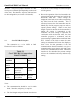
OmniLink 5000 Feed Manual interface. This port is jumper selectable as a RS232C port or a RS-485 port depending on the needs of the feed. The data bits, stop bits, and baud rate are all configurable (see section 3 for details). 2.3 December 13, 1999 be set at zero or the settings from the serial port will be ignored. Coe CPEC/BG1 Interface The connection to a Coe CPEC or BG1 Electronic Feed is as follows: Table 2.
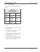
OmniLink 5000 Feed Manual 2.4 December 13, 1999 Coe BG2 Interface The connection to a Coe BG2 Electronic Feed is as follows: Table 2.
OmniLink 5000 Feed Manual 2.5 December 13, 1999 Coe ServoMaster Interface The connection to a Coe ServoMaster Feed uses two cables - an adapter cable to go from a telephone type connector on the operator interface of the ServoMaster to a DB-9 connector, and a longer cable to go from the DB-9 connector to the Link operator terminal.
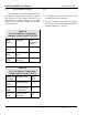
OmniLink 5000 Feed Manual 2.6 December 13, 1999 CWP ServoDial II Interface 2.7 CWP ServoDial 2000 Interface The connection to a CWP ServoDial II feed is as follows: The connection to a CWP ServoDial 2000 feed is as follows: Table 2.5 CWP ServoDial II Connections Link PN 107819 Table 2.
OmniLink 5000 Feed Manual 2.8 December 13, 1999 CWP Servomatic Interface Table 2.7 CWP Servomatic Connections Link PN 106744 The connection to a CWP Servomatic Feed is a little more involved than simply plugging in a cable. The servo control used in this feed, a reliance PRO200, is capable of “talking” to its own OIT or the OmniLink OIT but not both at the same time.
OmniLink 5000 Feed Manual 2.9 CWP ServoMax II Interface The connection to a CWP ServoMax II Feed (IQ2000/IQ5000 based) is as follows: December 13, 1999 2.10 Reliance/Electro-Craft IQ2000/IQ5000 Based Interface The connection to a Reliance or Electro-Craft IQ2000/IQ5000 based feed is as follows: Table 2.8 CWP ServoMax II Connections Link PN 105721 Table 2.
OmniLink 5000 Feed Manual 2.11 Dallas Feed Interface (EXOR Control) December 13, 1999 2.12 Emerson Servo Interface The connection to a Dallas feed with EXOR control is as follows: The connection to an Emerson Electronic Feed is as follows: Table 2.10 Dallas (EXOR Control) Connections Link PN 107865 Table 2.
OmniLink 5000 Feed Manual 2.13 Indramat CLM Interface December 13, 1999 2.14 Indramat DLC Interface Connections to the Indramat CLM are as follows: Connections to the Indramat DLC are as follows: Table 2.12 Indramat CLM Servo Connections Link PN 106739 Table 2.
OmniLink 5000 Feed Manual 2.15 Indramat SOT Interface December 13, 1999 The Indramat SOT (serial operator terminal) is sometimes used with CLM or DLC servo controls. When it is used, the OmniLink OIT must connect to the SOT instead of the CLM or DLC. Connections to the Indramat SOT are as follows: Table 2.
OmniLink 5000 Feed Manual 2.16 Indramat CLM Version 1.2 Interface This is an older version of Indramat firmware. Connections to the Indramat CLM are as follows: December 13, 1999 2.17 This is an older version of Indramat firmware. Connections to the Indramat SOT are as follows: Table 2.15 Indramat CLM Servo Connections Link PN 106739 OmniLink Feed Port Function / Color Indramat CLM Connector X6 Pin 1 (GND) Ground (WHITE) Pin 2 (RXD) Pin 3 (TXD) Indramat SOT with CLM Version 1.2 Interface.
OmniLink 5000 Feed Manual December 13, 1999 g) Select “Enable Relay Mode”. 2.18 PA Bullet/Edge/Advantage Interface The connection to a PA Bullet, Edge, or Advantage feed is a little more involved than simply plugging in a cable. The servo control used in this feed, a reliance PRO-200, is capable of “talking” to its own OIT or the OmniLink OIT but not both at the same time.
OmniLink 5000 Feed Manual 2.19 December 13, 1999 Rapid-Air Interface The Rapid-Air interface is somewhat different from most of the feed interfaces. Many of the feed functions are controlled from a small keypad and screen that connects to the only available communications port on the feed control itself. A special adapter board must be used to communicate with the feed. In addition, the old communications board needs an RS-232 to RS-485 converter to enable the System 5000 to communicate with the feed.
OmniLink 5000 Feed Manual December 13, 1999 Rapid-Air Connections with New Communications board The connections from the operator terminal to J58 must also remain in place. The connection to a Rapid-Air Feed from the new communications board is as follows: On the SC750 series of servo controls, Input 14 (Pin 6 of J56) must be low to enable remote download of feed parameters. On the SC950 series of servo controls, there is a circuit board below the communications connector with terminals on it.
OmniLink 5000 Feed Manual 2.20 December 13, 1999 2.21 Unico Interface Waddington Controller) Interface (MC500 The connection to a Unico Feed is as follows: The connection to a Waddington Feed is as follows: Table 2.21 Unico Connections Link PN 106746 OmniLink Feed Port Function / Color Unico Comm Board 25 Pin 232 Connector Pin 1 (GND) Ground (WHITE) Pin 2 (RXD) Pin 3 (TXD) Table 2.
OmniLink 5000 Feed Manual 2.22 December 13, 1999 Dynamic Feeds Interface The Dynamic Feeds interface is somewhat different from most of the feed interfaces. Many of the feed functions are controlled from a small keypad and screen that connects to the only available communications port on the feed control itself. A special adapter board must be used to communicate with the feed. This feed is only supported on the new communications board.
OmniLink 5000 Feed Manual 3. December 13, 1999 CONFIGURATION There are two different communication boards that have been used with the OmniLink 5000 referred to as the “old communication board” and the “new communication board”. See sections 2.1 and 2.2 to determine which of these is installed. Configuration of the feed interface depends on which of these boards is present. The following sections give configuration instructions for both boards. 3.
OmniLink 5000 Feed Manual Figure 3.1: Figure 3.3: OmniLink 5000 Communications Config. Screen Use the up and down arrow keys to highlight “Port 4" and hit the “CHANGE TASK” softkey until the description for port 4 reads “Feed - Not Configured” or has the name of a supported feed. Hit the “CONFIG TASK” softkey and a screen similar to Figure 3.4 should appear. Push the softkey for “OPERATOR TERMINAL”. A screen like Figure 3.2 should appear. Figure 3.
OmniLink 5000 Feed Manual Length Units - This is the unit in which to enter feed length values. Using the arrow keys, position the highlight cursor on this field and hit the “CHANGE SETTING” softkey until the desired length unit appears. This can be inch or millimeter. Note that this does not have to match the units the feed uses - the OmniLink will do the required unit conversion if necessary.
OmniLink 5000 Feed Manual the feed. Note that the units displayed to the right of the value should be set as well. To change the max acceleration, use the arrow keys to move the highlight cursor to the numeric “Max Accel” field. Enter the desired max acceleration using the numeric keypad and hit the “ENTER” key. To change the max acceleration units, use the arrow keys to move the highlight cursor the “Max Accel” units field (to the right of the number).
OmniLink 5000 Feed Manual 4. OPERATION There are two different communication boards that have been used with the OmniLink 5000 refereed to as “old communication board” and “new communication board”. See sections 2.1 and 2.2 to determine which of these is installed. Operation of the feed interface is virtually the same for both board, but small differences do exist. The following sections give operating instructions for both boards. 4.
OmniLink 5000 Feed Manual Feed Length - The current feed length setting. This value is displayed in whatever units were selected in feed configuration. To change the feed length, position the highlight cursor (while in program mode) on the feed length number, use the numeric keypad to enter the desired length, and hit the “ENT” key. The number will be sent to the feed and, for most feeds, verified. Any problems will be reported in the status field. Feed Speed - The current feed speed setting.
OmniLink 5000 Feed Manual Figure 4.3: Storing Job with Feed Off If the feed is off unintentionally, the operator may turn the feed ON and press the STORE SETUP softkey again to re-initiate the transfer of feed settings. If this job is to be performed without the feed, the CONTIN softkey instructs the operator terminal to ignore communication with the feed and store all other information for this job. If this is selected, zeros are stored for all feed parameters. 4.
OmniLink 5000 Feed Manual 5. December 13, 1999 INTERFACING TO OTHER FEEDS OR DEVICES In many cases a feed that is not currently supported may have a programmable basic module or other means of customization. You may also want to tie in a PLC or other controlling device that is handling an entire feed line. In these cases it makes sense to program the device to emulate (or “look like”) another already supported feed. The simplest feed to emulate is the Electro-Craft IQ2000 series.
OmniLink 5000 Feed Manual December 13, 1999 To Request Speed from the feed: 5000 Sends: G2[CR] Feed Returns: G2[CR][LF]G2[S]=[S]XXXX.XXXX[CR][LF][CR][LF]PDM> To Send Speed to feed: 5000 Sends: G2=XXXX[CR] Feed Returns: G2=XXXX[CR][LF]G2[S]=[S]XXXX.XXXX[CR][LF][CR][LF]PDM> For feed length the 5000 will send numbers from 000.000 to 999.999. For feed speed it will send 0000 to 9999. The normal use of feed speed has been to treat it as percent of maximum speed.
OmniLink 5000 Feed Manual December 13, 1999 Examples of Length set: Operator enters 3.255 for feed length. 5000 Sends: G1=003.255[CR] Feed Returns: G1=003.255[CR][LF]G1[S]=[S]3.2550[CR][LF][CR][LF]PDM> Operator enters .3 for feed length 5000 Sends: G1=000.300[CR] Feed Returns: G1=000.300[CR][LF]G1[S]=[S]0.3000[CR][LF][CR][LF]PDM> Examples of Speed set: Operator enters 5 for feed speed 5000 Sends: G2=0005[CR] Feed Returns: G2=0005[CR][LF]G2[S]=[S]5.
OmniLink 5000 Feed Manual December 13, 1999 G2=0100[CR][LF]G2[S]=[S]100.0000[CR][LF][CR][LF]PDM> 5.4 Manual Rev 2.
OmniLink 5000 Feed Manual Appendix A - Upgrading Link Equipment Link equipment may sometimes need software upgrades to take advantage of new features. The following sections explain how to do software and hardware upgrades. A.1 General Chip Changing Rules Changing the software on Link equipment is accomplished by swapping electronic chips called EPROMS (called “chips” in the rest if this section).
OmniLink 5000 Feed Manual December 13, 1999 Install the Channel 1 and 2 dual channel card Be sure not to leave any lockwashers or screws loose in the unit! Restore power to the System 1100. Make sure that the System 1100 resets. You should see a screen that look similar to: LINK SYSTEMS 1100 V2.7 OIT V2.5MB Figure A.1: System 1100 OIT Circuit Board A.2.2 System 1100 Motherboard Upgrade Procedure on the LCD for about 5 seconds after powerup. The main menu should then appear.
OmniLink 5000 Feed Manual A.3 OmniLink 5000 Upgrade Procedure Most OmniLink 5000 press controls shipped prior to July 1998 will need to have a hardware upgrade to work with LinkNet or to support certain feeds. This upgrade consists of replacing the old back plate and communications card on the operator interface terminal with a new back plate and communications card.
OmniLink 5000 Feed Manual December 13, 1999 Figure A.6: Operator Interface Terminal Circuit Board A.3.3 OmniLink OIT Communications Card Software Upgrade Procedure Figure A.5: Operator Interface Terminal to New Communications Board Connections A.3.2 OmniLink Procedure OIT Software Upgrade Note that older communications cards DO NOT have any software. This section applies ONLY to new communications cards. See Figures A.3 and A.4 to determine which card is present.
OmniLink 5000 Feed Manual December 13, 1999 Note that communications cards can have up to two additional software chips as options. Replace these chips only with chips that have the same labeling (except for the version)! Figure A.8: OmniLink 5000 Logic Module Circuit Board Insert the new 5000-A and 5000-B chips. Make absolutely sure that the “A” chip is in the “A” socket and the “B” chip is in the “B” socket. Insert the logic board in the card rack. Figure A.7: Communications Circuit Board A.
OmniLink 5000 Feed Manual Figure A.9: OmniLink 5000 Die Protection Module Circuit Board Insert the new 5000-7 chip. Insert the Die Protection board in the card rack. A.3.6 OmniLink Tonnage Monitor Module Software Upgrade Procedure This upgrade procedure applies only if the OmniLink control has an extended card rack and has the tonnage monitor module installed. Review the chip changing rules of section A.1. Remove power from the OmniLink card rack and the OIT.
OmniLink 5000 Feed Manual December 13, 1999 Figure A.11: OmniLink Auto-Setup Module Circuit Board Insert the new 5000-10 chip. If a module was removed from SS1, replace it. Insert the Auto-Setup Module in the card rack. A.7 Manual Rev 2.