TONNAGE MONITOR MODULE COLOR DISPLAY OPERATING MANUAL LINK ELECTRIC & SAFETY CONTROL COMPANY 444 McNALLY DRIVE, NASHVILLE TN 37211 PH (615)-833-4168 FAX (615)-834-1984 OmniLink 5000 System 5000 Press Control
Table of Contents Section 1 Introduction . . . . . . . . . . . . . . . . . . . . . . . . . . . . . . . . . . . . . . . . . . . . . . . . . . . . . . . . . . 1.1 Section 1.1 Features . . . . . . . . . . . . . . . . . . . . . . . . . . . . . . . . . . . . . . . . . . . . . . . . . . . . . . . . . . 1.1 Section 2 Parameter Entry and Access Control . . . . . . . . . . . . . . . . . . . . . . . . . . . . . . . . . . . . . . . Section 2.1 Parameter Entry . . . . . . . . . . . . . . . . . . . . . . . . . . . . . .
Section 4.2.2.6 Turning Reverse Limits ON or OFF . . . . . . . . . . . . . . . . . . . . . . . . . . . 4.8 Section 4.2.3 Setting Additional Data Window Parameters . . . . . . . . . . . . . . . . . . . . . . . . . . 4.8 Section 4.2.3.1 Turning Data Windows ON or OFF . . . . . . . . . . . . . . . . . . . . . . . . . . . 4.8 Section 4.2.3.2 Setting the Data Window “Start Angle” . . . . . . . . . . . . . . . . . . . . . . . . 4.8 Section 4.2.3.3 Setting the Data Window “End Angle” . . . . . . . . . . . . . . .
Section 5.1.8 End Sample Window Angle . . . . . . . . . . . . . . . . . . . . . . . . . . . . . . . . . . . . . . . . Section 5.1.9 Erase All Setups . . . . . . . . . . . . . . . . . . . . . . . . . . . . . . . . . . . . . . . . . . . . . . . . . Section 5.2 Machine Rating . . . . . . . . . . . . . . . . . . . . . . . . . . . . . . . . . . . . . . . . . . . . . . . . . . . . Section 5.2.1 Decimal Point . . . . . . . . . . . . . . . . . . . . . . . . . . . . . . . . . . . . . . . . . . . . . . . . . . .
April 17, 2000 Man ual Revisio n 1.
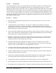
Section 1 Introduction The Tonnage Monitor module is an optional addition to the OmniLink 5000 Press Control intended to measure and display the force being applied to the frame of a mechanical power press. The force applied during the working portion of the stroke is compared with allowable limits based on the capacity of the machine and correct operation of the die and material being used.
press. A graph of tonnage versus crankshaft angle can be displayed for each channel or the total. This graph also shows the active areas of the data windows, when used. A reference waveform can be stored for each job. April 17, 2000 Man ual Revisio n 1.0 1.
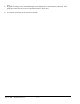
Section 2 Parameter Entry and Access Control Section 2.1 Parameter Entry Throughout the OmniLink control, a fairly standard form of data entry is employed. When data entry is allowed, an “editing cursor” will appear on the screen. This cursor can typically be moved from parameter to parameter on the screen with the up, down, left, and right arrow keys. The topmost softkey is used to select the parameter for editing and can change description depending on the parameter selected. Section 2.1.
Figure 2.1: Example Text Entry c) The fist character of the text is highlighted with the text cursor. The CURSOR LEFT and CURSOR RIGHT softkeys will move this cursor. d) Use the left and right arrow keys to point to the letter desired in the letter box next to the text being edited. This box will just appear above or just below the text to be edited depending on where it is in the screen. Hit the SELECT LETTER softkey to place that letter at the text cursor.
Section 2.2 Access Control The OmniLink control has several parameters or operations that have limited access. In regards to the tonnage monitor the ability to perform actions of turning bypass off and on, resetting faults, or changing limits must be restricted to certain personnel. The OmniLink control provides several means to limit access to these parameters or operations. These parameters and operations are called restricted items.
tonnage monitor limit. The example above can be taken one additional step, if two press operators are given different user names and different passwords. One operator can be assigned the ability to change tonnage monitor limits in addition to the ability to reset tonnage monitor faults, while the other operator is not assigned the ability to change the tonnage monitor limits. Section 2.2.3 Password Only Mode The “Password Only” mode allows for sixteen users.
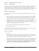
To gain access control the user must use one of two means or a combination of these two means. These means are the RUN/PROG key or the user password system. Section 2.2.6.1 RUN/PROG Key Switch Operation The RUN/PROG key switch is located on the lower right side of the operator terminal. This is a two position switch. The key is removable in the RUN position only. If the RUN/PROG key switch is being used as a means to access the restricted items, the switch must be turned to the PROG position.
Figure 2.2: Password Entry Sequence Step A: Select the restricted item. In the example shown in Figure 2.2 the restricted item is Channel 2 High Limit. Once the parameter is selected then Softkey # 1, the upper vertical softkey (Softkey # 1 is highlighted in Figure 2.2) , will display the legend “SELECT”. Step B: A list of users that have access to this restricted item will appear. In the example shown in Figure 2.
have access to all restricted items that have been designated for his access. This access will remain until the user performs a log out or until the user is automatically logged out. The user can log out by using the ACC key. This key will directly switch the display to the Quick Access screen. The LOGOUT soft key legend will appear along the bottom of the screen. If the operator presses this key, he will log out. He will no longer have access to the restricted items, unless he repeats steps A through D.
Section 3 Definitions and Terminology This section will give some background and explain the meaning of various settings and readings in the tonnage monitor. It is strongly recommended that this section be read in order to use the tonnage monitor effectively! Section 3.1 Tonnage The tonnage monitor reads forming forces (“tonnage”) from strain gauges mounted on the machine frame. Each strain gauge is a “channel”. Tonnage monitors typically have two or four strain gauges depending on the type of machine.
tons and both punches impact the material at the same position in the stroke (at the same time) the graph in Figure 3.2 shows the forces applied to the left and right sides of the machine frame along with the resulting total force. This process would result in the tonnage monitor displaying 100 tons for the left channel, 100 tons for the right channel, and 200 tons for the total. Figure 3.
stroke, the punch on the right contacts the material and exerts a total force of 100 tons at time t2, with 60 tons distributed to the right side of the machine frame and 40 tons distributed to the left. This process would result in the tonnage monitor displaying that the maximum tonnage measured on the left side of the machine frame was 60 tons, that the maximum tonnage measured on the right side of the machine frame was 60 tons, and that the maximum total tonnage exerted on the machine frame was 100 tons.
Section 3.2 Data Windows Peak tonnage monitors capture the maximum tonnage seen by each strain gauge over the stroke. This maximum tonnage is used for comparison to setpoints in determining if an alarm should be generated to stop the production process. While this is adequate for most applications, complex tooling can produce multiple peaks resulting in only the highest peak being checked against setpoints.
Section 3.2.2 Data Window Off Angle The Off Angle for a data window is the angle at which the setpoints for that data window stop being enforced. For example, in Figure 3.5, data window 1 has an off angle of 170 degrees. Section 3.3 Limits The tonnage monitor can compare the tonnages it reads to limits set for each job. The following sections detail these limits. Section 3.3.
Section 3.3.4 Reverse Limits A Reverse Limit should be set more negative than the maximum reverse tonnage developed when properly producing a particular part and is set for each channel of the tonnage monitor for the peak tonnage only. Data windows do NOT have reverse limits associated with them. If something in the process changes during normal operation that causes the tonnage developed to exceed this maximum reverse limit, a Top Stop Signal is provided to the press control in order to stop the process.
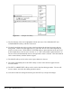
Section 4 Operation Section 4.1 Main Operator Terminal Screen The Operator Terminal Main Menu shown in Figure 4.1 provides the current status of the tonnage monitor module directly beside the TONNAGE MONITOR softkey. Figure 4.1: OmniLink Main Screen The status of the tonnage monitor module could indicate any of the following conditions: "OK" No tonnage alarms exist and no stop signals are being given by the module.
Section 4.2 Main Tonnage Monitor Screen The TONNAGE MONITOR softkey in the Main Menu provides access to the tonnage monitor module installed to operate with either two or four channels. This screen shows the maximum forward tonnages recorded during the last stroke, the description and status of each channel, the overall status of the tonnage monitor module, and limits that apply to the current view. Peak forward tonnage, peak reverse tonnage, and data window forward tonnages can be selected for viewing.
or other problems related to just that channel. c) Low Limit Value - The low tonnage limit setting for this channel and view (peak, data window 1, data window 2, etc). d) Graphical Limit Bar - This is a floating bar graph that graphically indicates where the tonnage for a channel is relative to the low and high setpoints for that channel. The bottom of the graph is the low limit and the top of the graph is the high limit.
Figure 4.3 shows a four channel screen when viewing data window tonnages. Notice that the major difference between this screen and that of Figure 4.2 is the addition of three new parameters and the lack of a REVERSE TONNAGE softkey. Figure 4.3: Example Data Window Tonnage View Referring to Figure 4.3, some additional settings in a data window view are: k) Data Window On/Off Setting - This determines whether the data window is active.
Figure 4.4 shows a four channel screen when viewing reverse tonnages. Figure 4.4: Example Peak Reverse Tonnage View Notice that there are no limit bars when viewing reverse tonnage as there is only one reverse limit for each channel. Referring to Figure 4.3, an additional setting in the reverse tonnage view is: n) Reverse Limit Value Section 4.2.1 - The reverse tonnage limit setting for this channel. Note that only peak tonnage has a reverse limit. Selecting a View As explained in section 3.
Section 4.2.1.1 Viewing the Peak and Data Window Tonnages and Settings The CHANGE VIEW softkey allows the operator to select which set of tonnages and settings are shown on the tonnage monitor screen. The view can be the maximum forward tonnage that occurred anywhere during the last stroke (Peak) or the maximum tonnage that occurred during a particular data window (Data Window 1 through Data Window 4). Each time the CHANGE VIEW softkey is hit the view will change.
To set a low limit, first choose the view and channel to change. Place the data entry cursor on a low limit setpoint (see “c” in Figure 4.2) using the up, down, left, and right arrow keys. Softkey 1 (The uppermost vertical softkey) should read “CHANGE LOW LIMIT”. Press this softkey to enter numeric entry mode. Enter the new limit with the numeric keypad and press the ENT key to set the limit.
Section 4.2.2.5 Turning Low Limits ON or OFF Pressing the LOW LIMITS ON/OFF softkey will toggle all low limits (including those in all data windows) ON or OFF. This key is only available when viewing forward tonnage (as in Figure 4.2 and Figure 4.3). Like changing setpoints, this is a restricted operation. The operator must have access to this operation via RUN/PROG Key or access code depending on how the system has been configured (See Section 2 for access configuration details).
window start to be enforced. To change the end angle, change the view to the data window desired. The screen should look something like Figure 4.3. Place the data entry cursor on the “End Ang” parameter (“m” in Figure 4.3). Softkey 1 (The uppermost vertical softkey) should read “CHANGE END ANGLE”. Press this softkey to enter numeric entry mode. Enter the new value with the numeric keypad and press the ENT key to set the angle. The end angle can be entered with a resolution of .
Section 4.3 Tonnage Alarms/Stop Conditions The Main Tonnage Monitor screen provides a status indication for each channel. This message indicates any tonnage alarm or error condition that has occurred and under normal operating conditions should show "Status: OK". If a tonnage alarm occurs, the message will change to reflect the FIRST alarm detected on that channel during the stroke. Section 4.3.
The Module Status in the bottom of the Main Tonnage Monitor screen will indicate "Tonnage Alarm". The Present Running Status in the Press Control screen will indicate "Tonnage Top Stop" or "Tonnage Cycle Stop". Section 4.3.3 High Data Window Alarm One of the messages listed below in the Channel Status indicates that the maximum tonnage recorded during the last stroke exceeded the High Limit setting in one of the data windows.
Section 4.3.5 Machine Rating Alarm A Channel Status message "Machine Rating" indicates that the maximum forward tonnage recorded during the last stroke exceeded 125 % of channel rating. When the condition is detected on any channel, a Cycle Stop is provided to the press control. This stop signal remains in effect and further stroking prevented until the alarm is RESET. The Module Status in the bottom of the Main Tonnage Monitor screen will indicate "Tonnage Alarm".
Section 4.4 Error Conditions Section 4.4.1 Setpoint Errors When power is applied to the OmniLink 5000 or when a limit has changed and the RUN/PROG keyed selector switch is in the RUN position, the tonnage monitor module performs a series of calculations based on the present limit settings. If an invalid condition is found to exist either due to an incorrect setting or an internal fault, an error message is generated in the Module Status and a Top Stop provided to the press control.
monitor and press the RESET ERROR softkey. If the error message does not return, connect the strain gauges one at a time to determine which gauge causes the shorted condition or verify that the resistance of each gauge (Vref to Gnd) is approximately 350 ohms. If the problem remains, it indicates a failure on the tonnage monitor analog board. Section 4.4.
Section 4.5 The Tonnage Monitor Graph Screen The GRAPH OPERATIONS softkey in the main tonnage monitor screen provides the operator or die setter more detailed analysis of machine forces by displaying tonnage versus crankshaft angle curves. The screen in Figure 4.5 shows an example screen when viewing peak tonnage information. Figure 4.6 shows the same example graph when viewing data window 2 information. Notice that the shaded softkeys in these figures change depending on the circumstances.
c) Reverse Limit Bar - This line (in red) graphically shows where the reverse limit is set with respect to the tonnage waveform. For a “good” hit, no part of the tonnage waveform should extend below this line. The “R” to the right of the line is for “Reverse”. d) Tonnage Waveform - This is the actual tonnage waveform collected by the tonnage monitor. The x-axis is crankshaft angle with 180 degrees being bottom dead center.
should not be confused with the start angle of a data window. Likewise, “END” is the graph end angle. This should not be confused with the end angle of a data window. Note that the ending angle may not always be exactly the value entered for this parameter but is calculated by the tonnage monitor due to the way it handles the waveform. “SCALE” is the percent of channel rating (or machine rating when viewing the total) displayed on the y-axis.
Figure 4.6 shows an example tonnage monitor graph screen when viewing a data window. For the most part, the screen is the same as when viewing peak tonnages. Figure 4.6: Example Tonnage Waveform With Data Window 2 Settings Selected for View Referring to Figure 4.6, some additional or different items on data window views are: n) Data Window Bars - The lower portion of the graph display is used to indicate the active area of the data windows.
p) Low Limit Bar - This line (in blue) graphically shows where the low limit is set with respect to the tonnage waveform. Notice that the line only exists where the data window is active. For a “good” hit, some part of the tonnage waveform between the data window start angle and the data window end angle should extend above this line. The “L” to the right of the line is for “Low”. q) High Limit Bar - This line (in red) graphically shows where the high limit is set with respect to the tonnage waveform.
Section 4.5.1.3 Graph Scale The graph scale (the number directly under “__SCALE__” in Figure 4.5) is the percent of channel rating (or machine rating when viewing the total) displayed on the y-axis of the graph. For instance, a 400 ton 4 channel machine will have a channel rating of 100 tons. If the graph scale is set to 100%, the maximum tonnage value shown on the graph will be 100 tons when viewing a channel, and 400 tons when viewing the total.
Assuming the operator has access (via RUN/PROG key or access code), the numeric keypad can be used to key in a new value or the decrement (m) and increment (l) keys can be used to decrement or increment the value. The graph will immediately reflect the changes made. Note that by holding down the decrement and increment keys the operator can effectively “drag” the setpoint graphically to where it needs to be.
this operation to succeed. When the “Send To Laptop” option of the SEND GRAPH softkey is selected, the OmniLink will retrieve the tonnage waveform from the tonnage monitor and transfer it to the laptop. The progress of the operations is shown at the top of the screen just above the tonnage graph in a special progress window.
a restricted operation and may require the RUN/PROG key and/or an access code depending on system configuration (see Section 2 for details). Section 4.5.4 Reference Waveforms For each job, one reference waveform may be stored. This will typically be a “known good” waveform representative of a setup that is producing good parts. If a problem, or suspected problem, later comes up with the job, the reference waveform can be “overlaid” with the current waveform to check for important differences.
April 17, 2000 Man ual Revisio n 1.0 4.
Section 5 Configuration The configuration menus of the tonnage monitor module are accessed by selecting the CONFIGURE TON MON softkey in the Main Tonnage Monitor Screen with the RUN/PROG keyed selector switch in the PROG position. The operator terminal will request entry of the configuration access code and upon correct entry will provide the configuration menu shown in Figure 5.1. Figure 5.1: Section 5.
Section 5.1.1 High Peak Alarm Stop This parameter defines the type of stop signal sent to the press control when a High Alarm occurs in the working portion of the stroke (View: Peak Tonnage). The following settings are allowed: Setting=000 This programs the tonnage monitor module to send a Top Stop signal to the press control. Setting=001 This programs the tonnage monitor module to send a Cycle (immediate) Stop signal to the press control.
Section 5.1.4 Channel Configuration The OmniLink 5000 tonnage monitor module contains strain gauge connections for four (4) channels. This parameter defines the number of channels that will be monitored by the module and should be set only when the module is first installed in the control. If this setting is changed from the way it was shipped from the factory, the OmniLink 5000 power must be turned OFF and back ON. The channel configuration is examined only at power up.
It has no effect on the determination of peak tonnage (sampled at 200 microseconds). Machines with speeds greater than about 20 strokes per minutes should be set to store at 200 microseconds. However, slower presses that begin the working portion of the stroke (Start of Sample Window) high in the downstroke may reach the maximum number of samples that can be stored (4735) before the end of the stroke is reached (End of Sample Window).
Section 5.2 Machine Rating This selection displays the screen shown in Figure 5.3. Changes are made with the RUN/PROG keyed selector switch in the PROG position by positioning the cursor onto the desired parameter with the arrow keys, using the numeric keypad to set a new value, and pressing the ENT key or through the softkeys provided. Figure 5.
If torque were the only limiting factor, the press could deliver infinite tonnage at the bottom of the stroke. However, the elastic limits of the press frame place an additional limitation near the bottom. Below the point where the machine is rated, an absolute maximum limit of 125% of rated capacity is placed on each strain gauge mounted to the machine frame in order to stop the machine before permanent damage is done to the structural members.
Section 5.3 Calibration Screens Section 5.3.1 Dynamic Calibration This selection displays the screen shown in Figure 5.5. Changes are made to the tonnage monitor calibration numbers (gain) with the RUN/PROG keyed selector switch in the PROG position by positioning the editing cursor onto the desired calibration number with the up, down, left, and right arrow keys as necessary. Softkey 1 (the uppermost vertical softkey) will change to read “CHANGE CAL NUM”.
softkey and use the alphanumeric selection method described in section 2 to enter a new description. Section 5.4 Reset Alarm Counters This selection displays the screen shown in Figure 5.6. Counters are reset with the softkeys shown. Figure 5.6: April 17, 2000 Man ual Revisio n 1.0 Alarm Counters Screen 5.
Section 6 Job Setups In the OmniLink 5000, all pertinent information for the current job such as programmable limit switch setpoints and automatic feed settings can be stored for later use as a block of information called a "job setup". Since this programmed data may change from job to job or as machine dies are changed, saving a job setup prevents the operator from having to manually change all this information when dies are changed.
used to prevent tonnage alarms from occurring, it will bypass ALL alarms (except machine rating alarms). Instead, it is suggested that the High Limits and Reverse Limits active during the working portion of the stroke (View: Peak Tonnage) be set for the approximate tonnage rating of the die. The Low Limits will be automatically disabled in Inch or Timed Inch modes.
Section 7 Installation Section 7.1 Module Location Figure 7.1 shows the OmniLink 5000 with the optional expansion rack and Tonnage Monitor Module installed. The module must be securely screwed to the card rack with the knurled screws attached to the faceplate of the card. Figure 7.1: April 17, 2000 Tonnage Monitor Module Installed in Card Rack. Man ual Revisio n 1.0 7.
Section 7.2 Strain Gauge Locations Section 7.2.1 "C" Frame Machines Machines with "C" frame configurations, such as OBI and GAP frame presses, should be installed with one strain gauge mounted to each side frame member and the tonnage monitor module configured for 2 channel operation. Choices of strain gauge mounting locations are illustrated in Figure 7.2. The preferred mounting locations are near the middle of the front of the "C" frame.
although ease of installation usually dictates mounting the strain gauges on the uprights. On solid frame straight side machines, the uprights are also the best strain gauge locations. The best strain gauge locations are below gibs and at least 12 inches above where the upright joins the machine bed. Locating the strain gauge in the gib region can cause excessive bending moments to be translated through the gibs into the upright as the slide tries to "cock" for some conditions of eccentric loading.
Figure 7.4 shows areas to avoid on uprights of straight side machines of tie rod construction. The crosshatched areas should be avoided. Figure 7.4: April 17, 2000 Areas to Avoid on Straight Side Machines (Do Not Mount in Cross- Hatched Areas) Man ual Revisio n 1.0 7.
On solid frame straight side machines, the preferred strain gauge mounting location is inside the "windows" under the ends of the crankshaft. A strain gauge should be mounted on the inside face of each column forming the "windows" as shown in Figure 7.5. Figure 7.5: April 17, 2000 Strain Gage Mounting on Solid Frame Straight Side Machines Man ual Revisio n 1.0 7.
April 17, 2000 Man ual Revisio n 1.0 7.
Section 7.3 Strain Gauge Mounting Strain gauges may be bolted directly to the machine or bolted to intermediate pads welded or adhered to the machine. Section 7.3.1 Direct Machine Mounting 1) Select the desired mounting locations for the strain gauges. 2) Remove paint, oil, grease, etc., to obtain a bare metal surface slightly larger than the LST-1000 strain gauge. The metal surface must be flat and smooth so that the strain gauge is not warped and contacts the surface area evenly when mounted.
mounting holes may slightly change the strain sensed by the strain gauge. Section 7.3.2 Intermediate Weld Pad Mounting 1) Select the desired mounting locations for the strain gauges. 2) Remove paint, oil, grease, etc., to obtain a bare metal surface slightly larger than the LST-1000 strain gauge. 3) Clean the mounting surface with a solvent, removing all contaminants. 4) Assemble the intermediate pads to the alignment/clamping fixture using the 1/4 x 28 bolts provided, as shown in Figure 7.8.
Section 7.4 Strain Gauge Wiring 1) Run flexible or rigid conduit from the strain gauge protective boxes to the control enclosure that contains the OmniLink 5000 card rack. Entry into the control enclosure should be as close as possible to the tonnage monitor module. 2) Pull the strain gauge cables through the conduit from the strain gauge locations to the control enclosure. Once inside the enclosure route the strain gauge cables away from all other voltage sources, as much as possible.
Section 7.5 1) Installation Procedure Position the press at the top of the stroke, turn power to the machine off, and install tonnage monitor card in the OmniLink 5000 card rack. Make certain both knurled screws that hold the module in place are tight (see Section 7.1). If this installation is replacing a System 1000/1100 tonnage monitor already installed on the machine, before turning power OFF, write down the present machine rating and cal #'s.
13) Exit back to the Tonnage Monitor Screen and enter high limits and low limits (for Peak Tonnage and all Data Windows). Enter reverse limits. The tonnage monitor is shipped from the factory with low, high, and reverse limits programmed. If the installation procedure required the machine rating to be changed, these limits may no longer be acceptable and could generate an error condition. April 17, 2000 Man ual Revisio n 1.0 7.
Section 7.6 Configuring Control The OmniLink 5000 press control must be configured to allow the tonnage monitor module option. The installation procedure is as follows: 1) From the Main Menu screen, select the PRESS CONTROL softkey. 2) Switch the RUN/PROG keyed selector switch to the PROG position. 3) Select the CONFIGURE softkey and enter the Configuration Code. 4) Select MACHINE PARAMETERS. The Machine Parameters menu will appear. 5) Select the FACTORY CONFIG softkey.
April 17, 2000 Man ual Revisio n 1.0 7.
Section 8 Calibration Calibration of an OmniLink 5000 Tonnage Monitor Module consists of achieving a known load on the machine and adjusting the installed monitor so that the known load is displayed correctly. The known load used during calibration should be at least 50% of rated machine load and preferably 100% of rated machine load.
CAUTION! Extreme care should be used in calibration procedures for tonnage monitors. Severe damage to the machine being calibrated or the calibration equipment can result from incorrect shut height adjustments. Injury to personnel calibrating the machine or to others in the machine area can result from poorly implemented load cell or hydraulic jack stacks that fly out of the machine under load.
Section 8.1 Dynamic Calibration with Load Cells a) Check to see that the OmniLink 5000 Tonnage Monitor Module is installed as per the installation instructions of this manual. b) Turn on the power to the OmniLink 5000. Observe that the OmniLink 5000 tonnage monitor module displays zero. If the tonnage displays fail to zero within 40 seconds or an error occurs, check that the strain gauges are wired correctly into the channel connectors and refer to error conditions listed in this manual.
On mechanical power presses with shut height adjustments, the stack height should be greater than the minimum shut height, and the machine shut height must be adjusted so that clearance between the machine slide and the load cell stack(s) is provided.
Vibratory motion in the machine often introduces stroke to stroke variations of one or two percent in the load cell tonnage readings. When this happens it is impractical to try to refine the load on the machine any closer than within one or two percent of rated tonnage.
Section 8.2 Static Calibration with Hydraulic Jacks a) Check to see that the OmniLink 5000 Tonnage Monitor Module is installed as per the installation instructions of this manual. b) Turn on the power to the OmniLink 5000. Observe that the OmniLink 5000 tonnage monitor module displays zero. If the tonnage displays fail to zero within 40 seconds or an error occurs, check that the strain gauges are wired correctly into the channel connectors and refer to error conditions listed in this manual.
i) Access the T/M Configuration menu of the OmniLink 5000 Tonnage Monitor Module, select Calibration and Channel Description (refer to Section 5.3). The T/M Calibrate menu will appear. Press the STATIC CAL softkey to enter the Static Calibration mode. The top of the screen will read “Tonnage Monitor Static Calibration Mode.” With the RUN/PROG keyed selector switch in the PROG position enter a calibration number of 400 into each channel.
files. o) Press the EXIT softkey and return to the Tonnage Monitor menu. Calibration is complete. April 17, 2000 Man ual Revisio n 1.0 8.
Section 8.3 Replacing System 1000/1100 If the OmniLink 5000 Tonnage Monitor Module is replacing a System 1000 or System 1100 Tonnage Monitor that is already installed on the machine and calibrated, the calibration numbers from the System 1000/1100 can be transferred to the OmniLink 5000. This is done by accessing the configuration menus of the OmniLink 5000 Tonnage Monitor Module and selecting Calibration and Channel Descriptions.
April 17, 2000 Man ual Revisio n 1.0 8.
Section 9 Troubleshooting Section 9.1 Communication Failure The message "Communication Failure" in the tonnage monitor status line of the Main Operator Terminal screen indicates that the operator terminal can not establish serial communication with the module. Since this serial interface is used to communicate will all boards in the OmniLink 5000 card rack, the problem may be that the display can not communicate with any of the boards.
April 17, 2000 Man ual Revisio n 1.0 9.
Section 10 Section 10.1 Software Version The information in this manual is based on tonnage monitor software version 1.08 Section 10.2 Configuration Code and Clear Stroke Counter/Memory Code The Configuration Code used to gain access to the tonnage monitor configuration menus is the same Configuration Code as used by the OmniLink 5000 press control.