COLOR DISPLAY OPERATING MANUAL LINK ELECTRIC & SAFETY CONTROL COMPANY 444 McNALLY DRIVE, NASHVILLE TN 37211 PH (615)-833-4168 FAX (615)-834-1984 OmniLink 5000 System 5000 Press Control
TABLE OF CONTENTS Section 1 Introduction . . . . . . . . . . . . . . . . . . . . . . . . . . . . . . . . . . . . . . . . . . . . . . . . . . . . . . . . . . . 1.1 Section 1.1 System Overview . . . . . . . . . . . . . . . . . . . . . . . . . . . . . . . . . . . . . . . . . . . . . . . . . 1.1 Section 2 Operator Terminal . . . . . . . . . . . . . . . . . . . . . . . . . . . . . . . . . . . . . . . . . . . . . . . . . . . . . . Section 2.1 LCD Description . . . . . . . . . . . . . . . . . . . . . . . . . . . .
Section 4.3.1 Setup/Stop Time Test . . . . . . . . . . . . . . . . . . . . . . . . . . . . . . . . . . . . . Section 4.3.2 Timed Inch (When Provided) . . . . . . . . . . . . . . . . . . . . . . . . . . . . . . . Section 4.3.3 Inch . . . . . . . . . . . . . . . . . . . . . . . . . . . . . . . . . . . . . . . . . . . . . . . . . . . Section 4.3.4 Single Stroke . . . . . . . . . . . . . . . . . . . . . . . . . . . . . . . . . . . . . . . . . . . . Section 4.3.5 Continuous . . . . . . . . . . . . . . . . . . .
Section 5.1.1.2 Single Speed Presses, Link Standard . . . . . . . . . . . . . . . . . . . . 5.5 Section 5.1.2 Top Stop Calibration, Link High Speed . . . . . . . . . . . . . . . . . . . . . . . . . 5.5 Section 5.1.2.1 Variable Speed Presses, Link High Speed . . . . . . . . . . . . . . . . 5.7 Section 5.1.2.2 Single Speed Presses, Link High Speed . . . . . . . . . . . . . . . . . . 5.8 Section 5.1.3 Stop Angle (Setup Mode) . . . . . . . . . . . . . . . . . . . . . . . . . . . . . . . . . . . 5.8 Section 5.
Section 5.4.7 Configure Auxiliary Communications . . . . . . . . . . . . . . . . . . . . . . . . . Section 5.6 Output Names/Messages . . . . . . . . . . . . . . . . . . . . . . . . . . . . . . . . . . . . . . . . . . Section 5.6.1 Input Names (option) . . . . . . . . . . . . . . . . . . . . . . . . . . . . . . . . . . . . . Section 5.6.2 Aux. Equipment Messages . . . . . . . . . . . . . . . . . . . . . . . . . . . . . . . . . 5.21 5.22 5.22 5.23 Section 6 Press Control I/O . . . . . . . . . . . . . . . .
Section 7.2.7 Motor Current . . . . . . . . . . . . . . . . . . . . . . . . . . . . . . . . . . . . . . . . . . . Section 7.3 Calibrating Flywheel Speed Interface . . . . . . . . . . . . . . . . . . . . . . . . . . . . . . . . . Section 7.3.1 Calibrating Flywheel Speed Display . . . . . . . . . . . . . . . . . . . . . . . . . . . Section 7.4 Communication Option . . . . . . . . . . . . . . . . . . . . . . . . . . . . . . . . . . . . . . . . . . . Section 7.5 System Startup . . . . . . . . . . . . . . . . .
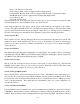
Section 1 Introduction The System 5000 Press Control is designed specifically for use on part revolution mechanical power presses. Two separately powered microprocessor systems each perform clutch/brake control logic independently and cross communicate with each other to check control agreement. All inputs are isolated and read independently by each channel. A combination resolver and encoder assembly is read and checked independently by each channel.
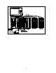
Figure 1.1 System Components 1.
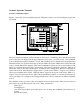
Section 2 Operator Terminal Section 2.1 LCD Description Figure 2.1 shows the operator terminal front panel. This panel consists of a color LCD display, keypad, and key switch.
-Press Control Reason for Last Stop -Total Tonnage (If the control is equipped with a tonnage monitor) -Counterbalance Pressure (If the control is equipped with automatic counterbalance adjust) -Shut Height (If the control is equipped with automatic shut height adjust) -Current Order Count -Current Down Time Code These four items are also mode dependent. The user has the option to chose four items for setup modes, Inch and Timed Inch modes, and four different items for production modes.
the present number being entered, and the entry process is aborted by pressing the EXIT softkey or one of the arrow keys. The numeric data will not change from the previous value if the entry process is aborted. Section 2.7 Alphanumeric Data Entry Items that require the entry of both letters and numbers will automatically provide the Text Entry menu shown in Figure 2.2.
Section 3 Access Control Section 3.1 Description The OmniLink control has several parameters or operations that have limited access. The ability to perform actions such as job recall, job storage, or changing a tonnage monitor channel limits must be restricted to certain personnel. The OmniLink control provides several means to limit access to these parameters or operations. A complete list of the parameters and operations that have limited access is listed in Section 3.2. The items in Section 3.
die set-up personnel. A press operator is assigned a user name and password. With the password the operator can reset tonnage monitor faults, reset die protection faults, and reset counters. These are the only three items to which the operator has access. In order to load a die, the set-up personnel must use the Program/Run key to recall a job from job storage. The set-up personnel will also be able to make changes to programmable limit switch settings, tonnage monitor settings, and die protection settings.
Section 3.2 Restricted Items The following table lists the restricted items name and function.
19 PLC Screen 1 Sets Change parameters on Screen 1 of the Programmable Logic Controller Interface 20 PLC Screen 2 Sets Change parameters on Screen 2 of the Programmable Logic Controller Interface 21 PLC Screen 3 Sets Change parameters on Screen 3 of the Programmable Logic Controller Interface 22 PLC Screen 4 Sets Change parameters on Screen 4 of the Programmable Logic Controller Interface 23 Special Interface Change parameters on the Special Interface Screen 24 Auto SS/COD Time Change the A
items. All restricted items are accessible when the Program/Run key switch is switched to the PROG position. When operating in the “Key or Password” mode, the key switch is one of the means available to access the restricted items. All restricted items are accessible when the Program/Run key switch is switched to the PROG position. When operating in the “Key and Password” mode, the key switch and password must be used to access the restricted items.
Step A: Select the restricted item. In the example shown in Figure 3.1 the restricted item is Motor Speed. Once the parameter is selected then Softkey # 1 the upper vertical softkey (Softkey # 1 is highlighted in Figure 3.1) , will display the legend “SUPPLY ACCESS CODE”. The operator must press this softkey. Step B: A list of users that have access to this restricted item will appear. In the example shown in Figure 3.
3.
Section 4 Operating Menus Section 4.1 Main Menu Figure 4.1 shows the Main Operating Menu. This screen provides an overall view of the functions available along with pertinent information for each. From this menu the operator may select the Press Control, Programmable Limit Switch, Automatic Setups (with optional board installed), Tonnage Monitor (with optional board installed), Die Protection (with optional board installed), Job Setups, Counters, and Motor Speed Adjust.
6. The status of the order and batch counter. This includes the preset limit, the present quantity produced, and the on/off state of the counter. 7. A bar graph which represents the current main motor speed. 8. A bar graph which represents the current main motor load. Section 4.2 Press Control Menu Figure 4.2 shows the Press Control Menu. This screen provides detailed information about the press, the press control, and auxiliary equipment.
7. Continuous on Demand Time 8. Messages from auxiliary equipment. 9. The event that caused the press to stop. 10. The event that is keeping the press from running, if any exists. If configured, the Motor Speed Adjust screen can be accessed from this screen in order to change the stroking speed of the press (see Section 4.7). In addition the Tonnage Monitor, Auto Setups, and the Die Protection can be accessed from this screen if so configured. Section 4.2.
a die protection module the press control will also wait for all die protection inputs to become satisfied. The maximum time allowed for successive automatic strokes initiated by the feed is configured by the factory, and is set for 10 seconds unless a specific application requires otherwise. Any stop input that causes a stroke to not be initiated within this time limit will require clearing the fault and manually re-initiating the stroke.
Section 4.2.7 Reason For The Last Stop Diagnostic information is provided to show the reason the press stops. Once a stroke is initiated, the first stopping action is latched and displayed. This is done to capture transient conditions that may return to their proper state after the press stops. This information remains latched until press stops again. Additional information concerning press stops is archived in the Event Log. See Section 4.2.9.4. Section 4.2.
0 TOP Num 1 2 3 4 5 6 7 8 9 10 11 12 13 14 15 16 17 18 19 20 21 22 23 24 0 Stroke Mode Single Stroke Order Counter 0 SPM 0 SPM Input Module 1 Name Type T-STOP E-STOP E-STOP E-STOP E-STOP Drive Speed Stroke Speed L. N.O. INCH BUTTON R. N.O. INCH BUTTON L. N.O. STATION # 1 R. N.O. STATION # 1 L. N.O. STATION # 2 R. N.O. STATION # 2 L. N.O. STATION # 3 R. N.O. STATION # 3 L. N.O. STATION # 4 R. N.O. STATION # 4 ALL N.C.
Group 2 Programmed in Top Stop Calibration (configuration).
Group 5 Programmed in Factory Mode Configuration. 45 Allow Timed Inch 46 Allow Auto Single Stroke 47 Allow Continuous on Demand 48 Allow Maintain Continuous 49 Maximum Auto Single Stroke time 50 Max. Continuous on Demand time (value) (value) (value) (value) (value) (value) Section 4.2.9.4 Event Log The controls retains a event log. This log records the reason for the last 128 stops. All reasons for last stop are recorded, except automatic stop on top.
0 TOP 0 Stroke Mode Single Stroke Drive Speed Stroke Speed 0 SPM 0 SPM SPM 0 Order Counter Counter OFF PC STATUS READY TO STROKE % LOAD 161 PRESS CONTROL Brake Monitor Limit Stoptime Top Stroke Stop Mid Stroke Stop 0200 0250 208 0 mSec mSec Clutch time Limit 0275 Actual 0250 mSec MOTOR SPEED Sec Degs Mins TONNAGE MONITOR Auto Single Stroke Time ……… 5 Feed Complete Position ……… 25 Cont. on Demand Time ……….
the RUN position. The display automatically presents one of the menus shown in Figure 4.7 and allows the operator to choose from one of the stroking modes shown or select the other page of modes. The present mode is shown at the top of the LCD, and a new mode is selected by pressing the desired softkey. The display will remain in one of the two menus shown until the mode selector is returned to the RUN or OFF position.
Section 4.3.2 Timed Inch (When Provided) This mode selection functions like the Inch mode until a programmable downstroke slide position is reached. After this point, holding the Inch buttons depressed results in automatically controlled inching movements of the slide until the dies resist slide motion or until the bottom of the stroke is reached. When the bottom of the stroke is reached, the clutch action will stop.
emergency stop, or other stop input occurs. In the event of any stop condition, further strokes can be initiated only after all operator run buttons and the Continuous Setup button are released. Stroke initiation is prevented if an inactive station run button is depressed. If station #4 is configured for a foot switch, stroke initiation is prevented if the foot switch is selected. Only the active palm button stations may be used to initiate a stroke in this mode.
prevent further automatic stroking until the stop conditions are removed and automatic stroking is manually initiated. Stroke initiation is prevented if an inactive station run button is depressed. If station #4 is configured for a foot switch, stroke initiation is prevented if the foot switch is selected. Only the active palm button stations may be used to initiate a stroke in this mode. Stroking is allowed only when the main motor is on and running in the forward direction.
0 Stroke Mode Single Stroke TOP 1 Ch 0 On Off Drive Speed Stroke Speed 3 2 180° 30° 40° 270° 90° 0° 0° 0° Counter OFF PC STATUS READY TO STROKE On/Limit Off/Cnt 0 01 02 03 04 05 06 07 08 Order Counter 0 SPM 0 SPM .30 Sec 40° 50° .
To bypass an output: 1. The operator must have access control. Access control is described in Section 3. If the user obtains access control by using the password system, the user must be configured to have access to bypass the programmable limit switch outputs. 2. Use the arrow keys to position the cursor onto the desired channel. 3. If the programmable limit switch channel is currently On, not Bypassed, press the BYPASS ON/OFF softkey to Bypass the channel. 4.
descriptions to particular outputs of the current job. The menu in Figure 4.9 shows the output descriptions available as two pages of fifteen names. The output number to which the description is being assigned is displayed at the bottom of the screen.
Section 4.4.4 Restricted PLS Channels Any programmable limit switch channel that has been restricted in the Press Control Configuration Menu cannot be altered or bypassed by the operator. Only the first eight channels, PLS 1 to 8, can be restricted. A restricted channel is indicated as being restricted by an "R" after the channel number in the Description section of the Limit Switch menu. The softkeys that allow changes to be made to do not exist for restricted channels.
The display provides the following information: 1. A list of all jobs presently in the internal file storage. The jobs are identified by a 9 digit number, and a 20 character description. A total of 500 jobs can be stored, and are shown in groups of up to 15. 2. The current job being used by the press control. Section 4.5.1 Store Setup From the Jobs Menu, Figure 4.10, selecting the STORE SETUP softkey will transfer the screen to the Store Jobs menu.
access control by using the password system, the user must be configured to have access to recall jobs from memory. The Select Job menu is shown in Figure 4.12. There are two ways to select a job. The first way is to enter the job number, if it is known. The ENTER NUMBER softkey allows the user to enter the desired job number directly into the operator terminal, which automatically searches the file system and retrieves the job if located. The second way is to select the job from the screen.
From the Jobs Menu, Figure 4.10, depressing the ERASE SETUP softkey will transfer the screen to the Select Job menu. The Select Job menu allows the user to select the job that is to be erased. The user must have access control to perform a job erase. Access control is described in Section 3. If the user obtains access control by using the password system, the user must be configured to have access to erase jobs from memory. The method for locating a job is the same as those for recalling one.
5. Current Scrap Count and Scrap Rate Section 4.6.1 Production Counters The OmniLink control has up to ten production counters. The first three production counters have dedicated names. These are Order, Batch and Quality. These three counters will always appear on the screen. The other seven counters are auxiliary counters. Auxiliary counters can be enabled or disabled in the counter configuration. If an auxiliary counter is enabled in the counter configuration, it will appear on the screen.
Production counters can be turned on or turned off. The user must obtain access control in order to turn the counters on or off. Access control is described in Section 3. If the user obtains access control by using the password system, the user must be configured to have access to change counter settings. When a counter is turned off, it does not increase. In addition, a counter that is turned off cannot issue a stop to the press control.
must be configured to have access to change counter settings. To increase or decrease the current count value by one, select the counter and depress either the INCREMENT or DECREMENT softkey. To select a counter, use the arrow keys to position the cursor on the counter that is to be changed. The cursor can be either in the COUNT column or in the LIMIT column.
To change the value of the scrap count, position the cursor on the scrap counter and select the CHANGE SCRAP softkey. Then enter the new count using the numeric keypad. After the correct value is entered, press the ENT key. If the scrap count is increased, the amount by which it is increased is subtracted from the production counters. If the scrap count is decreased, the amount by which it is decreased is added to the production counters.
0 TOP 0 Stroke Mode Single Stroke COUNTER NAME Order Counter Batch Counter Quality Counter Aux 1. Counter Aux 2. Counter Aux 3. Counter Aux 4. Counter Aux 5. Counter Aux 6. Counter Aux 7.
CHANGE Strokes softkey, enter the new number, and press the ENT key Section 4.6.4.4 Configure Counter Reset When Order Counter Reset All counters other than the Order counter can be reset in two ways. The counters can be individually reset or the counter can be reset when the Order counter is reset. To change the Reset When Order Counter Reset setting of a counter position the cursor on the value to be changed, press the CHANGE SETTING softkey. Section 4.6.4.
Spm. In this situation, the operator can enter a speed setting up to 400 in any mode but the command signal to the drive will go no higher than 250 spm when Single Stroke mode is selected (i.e. it will clamp at the configured limit). In addition, the press control can be configured to command a fixed speed in Inch and Timed Inch modes in which case the operator’s speed setting will not take place until the appropriate stroking mode is selected.
0 TOP 1 0 Stroke Mode Single Stroke Drive Speed Stroke Speed 200 SPM 0 SPM Order Counter Counter OFF PC STATUS Ready to Stroke QUICK ACCESS CURRENT LOGIN IN: OPERATOR # 1 2 MACHINE NOTES Press lube should be type xyz. Check level daily Flywheel belt deflection should be not more that 1” at midpoint. 3 EDIT NOTES NOTES FOR JOB # 1 Use material lube abc for this part Material should have a maximum thickness of .161 AUXILIARY COMM. LOGOUT EXIT Figure 4.
In order for the job notes to be saved after editing, the current job must be stored. Job storage is described in Section 4.5.1. Section 4.8.4 Auxiliary Communications The AUXILIARY COMM softkey will provide access to communication options. These options include communication with electronic servo feeds, auxiliary equipment (such as PLCs), a laptop interface for downloading messages, and a network interface. See the manual pertaining to the particular device that is connected for communication. Section 4.8.
Section 5 Press Control Configuration Menus The System 5000 allows the user to configure the control and the operator terminal for specific machine requirements. This restricted menu section is accessed from the Press Control menu. The Configuration softkey is available only in the Program/Run switch is in the PROG position. The Press Control menu with the Program/Run switch in the PROG position is shown in Figure 5.1.
Section 5.1 Top Stop Calibration There are two versions of Top Stop Calibration. These are Link Standard and Link High Speed. The Link Standard Top Stop calibration is for Link controls that supports the standard stop on top algorithm. Link standard controls are intended to be used on presses that can stop in 180 degrees or less when stroking at their maximum speed. The screen for this standard top stop calibration is shown in Figure 5.3. Sections 5.1.1, 5.1.1.1, and 5.1.1.
1 0 TOP 0 Stroke Mode Single Stroke 2 3 4 Drive Speed Stroke Speed 200 SPM 0 SPM Order Counter Program/Run Switch TOP STOP CALIBRATE Speed Advance Top Stop Stroking Mode 5 6 Single Continuous Speed and Stopping Angle 50 100 150 340 338 7 [ Speed Ch A 050 Ch B 050 8 Stop Pos (Setup Mode) = 090 Counter OFF PC STATUS 330 328 Calculated } Top Ang 340 340 320 318 200 RPM CHANGE NUMBER 310 308 Measured Stop Ang 340 340 MOTOR SPEED EXIT Figure 5.
If configured, the Motor Speed Adjust screen can be accessed from this screen in order to change the stroking speed of the press (see Section 4.7). Section 5.1.1.1 Variable Speed Presses, Link Standard Variable speed presses require a calibration procedure be performed when the press control is installed. This process uses the top stop characteristics of the press at four programmed speeds. The suggested top stop calibration procedure is as follows: 1.
8. Set the flywheel speed to the highest speed range. Repeat Steps 4 and 5. 9. Repeat steps 3, 4, 5, 6, 7, and 8 with the press in Continuous mode. In this mode the four top stop angles shown on the line labeled Continuous (line 6 above) affect the stopping characteristics of the press. These parameters are used during this portion of the calibration process. The Top Stop button should be used to cause the press control to initiate a stop on top. Section 5.1.1.
0 TOP 0 Stroke Mode Single Stroke Drive Speed Stroke Speed 200 SPM 0 SPM Order Counter Counter OFF PC STATUS Program/Run Switch TOP STOP CALIBRATE Speed Adjusted Top Stop Manual Stroking Modes 1 Speed Low-High Top Stop . . . . . . 0020 0010 0100 0050 RPM BTDC 0300 0200 RPM BTDC CHANGE NUMBER Continuous Stroking Modes 2 Speed Low-High Top Stop . . . . . . 0020 0010 3 [ Speed Ch A 100 Ch B 100 Calculated } Stop Ang 340 340 4 Stop Pos (Setup Mode) = 090 MOTOR SPEED EXIT Figure 5.
Variable speed presses require a calibration procedure be performed when the press control is installed. This process involves running the press at both a low and high speed and adjusting the top stop position (programmed in Degrees Before Top Dead Center) to stop the press at the top of the stroke at both speeds. This procedure must be performed for both manual stroking modes and continuous stroking modes. The suggested top stop calibration procedure is as follows: 1.
generated the correct stopping curve. 3. With the Program/Run switch in the RUN position, select Continuous mode. 4. The same top stop calibration procedure as described above can be performed for Continuous stroke modes (area 2 in Fig. 5.4). It should be possible to use the manual stroke mode settings as a starting point and then make adjustments at the low and high speeds to compensate for different stopping characteristics in continuous stroking modes.
0 TOP 0 Stroke Mode Single Stroke Drive Speed Stroke Speed 200 SPM 0 SPM Order Counter Counter OFF PC STATUS Program/Run Switch MACHINE PARAMETERS Parameter Encoder Offset…………………….. Auto Carry Up …………………….. Begin Timed Inch…………………. Minimum Strokes / Min ………….. Maximum Strokes / Min …………. Motion Filter ………………………. Clutch Engagement ……………... Timed Inch Pulse ………………… Automatic Turn Off ………………. Max. # Engage/Min ……………….. Top Stroke Stop Time ……………. Mid Stroke Stop Time …………….
the nearest acceptable rpm. Section 5.2.5 Maximum Strokes/Minute This parameter also appears in the Configure Speed screen and can also be programmed in that screen. See Section 5.2.13.1. This parameter is used to scale the analog input of flywheel speed to the R/D board for variable speed presses. A full scale input (+5 volt on the A/D converter) is considered to be this speed and all other inputs are scaled accordingly.
provided as an energy conservation feature. After this time has elapsed, the press control will turn its LMC relay off until the main motor turns off. This value is limited to between 0 and 250 minutes, and an entry beyond the limit is rejected. An entry of 0 disables this feature. Section 5.2.10 Maximum # Engagements per Minute This parameter sets the maximum number of times that the clutch/brake valve can be energized and deenergized in any 1 minute interval.
at which the press will stroke in that mode. On variable speed presses that have high maximum stroking speeds for the Continuous mode, the stroking speeds in Inch and Single Stroke may be limited to prevent excessive clutch and brake wear. 0 TOP 0 Stroke Mode Single Stroke Drive Speed Stroke Speed 200 SPM 0 SPM Order Counter Counter OFF PC STATUS Program/Run Switch CONFIGURE SPEED Press Function Maximum Strokes/Min ……………….. Fixed Inch Spm………………………… Max Single Spm………………………..
Automatic Single Stroke, and can include Inch and Timed Inch if a fixed Inch speed has been turned off. The example shown in Figure 5.6 describes a press that has a maximum continuous stroking speed of 400 spm but has been configured to run no greater than 100 spm in single stroking modes. Note that this is not a fixed speed and that the motor speeds screen allows the speed to be set over the entire range.
Section 5.2.13.8 Low Spm Input Offset This parameter is used in the calibration procedure of the flywheel speed input to the press control. If needed, this parameter can be used to adjust the spm reading at low speed (see Section 7.3). Section 5.2.13.9 Low Output Spm This parameter is used to calibrate the analog output from the press control to the motor drive, and to define the low end of the speed range for this press. Operating speeds or configuration speeds (i.e.
command signal the motor drive only strokes the press at 220 spm. In this situation the Mid Output Spm can be set to 225 spm and the Mid Output Calibration # can be set to whatever output voltage is required to drive the press to 225 spm. For example, if 6.30 vdc is required to drive the motor to 225 the cal. # is set to (4095 x 6.30)/10.00=2580. If no adjustment at mid range is required this parameter along with the Mid Output Spm should be set to 0000. Section 5.2.13.
Section 5.3.1 Auxiliary Lube Systems (option) If the optional expansion card rack and third input board are provided, two auxiliary lube systems are added to the lube system menu as shown in Figure 5.7. These auxiliary lubes function independently, and allow for metered systems only. Each allows the time between lubrication cycles to be set in terms of the number of press strokes, variable from 10-99,990. A lube cycle duration time can be set for both normal operation and power up situations. See Section 6.
The displayed item can change when the press stroking mode is changed. The user can chose four items that are to be displayed in Setup modes, such as Inch and Timed Inch, and four items that are to be displayed in Production modes, such as Single Stroke and Continuous. The displayed items can be selected by positioning the cursor into the area that is to be changed and depressing the CHANGE SETTING softkey. A menu of items will appear on the screen. Only items that are not currently selected will appear.
To zero the stroke count, authorized personnel must enter a specific number and press ENT. The number that must be entered is the second code number listed in the Section 9.2. The present stroke count is displayed in the counter menu. Section 5.4.6 Access Configuration As described in Section 3 the user must gain Access Control in order to perform certain operations and change certain parameters.
To change the current access mode position the cursor on the current access mode, press the CHANGE SETTING sofkey, position the cursor to the desired access mode, press the ENT key. Section 5.4.6.2 Access Timeout When a user gains control access by using a password, he will logged in until he manually logs out or is automatically logged out. See Section 3.3.2. Automatic log out can be either time based or stroke based.
0 TOP 0 Stroke Mode Single Stroke Drive Speed Stroke Speed 0 SPM 0 SPM Order Counter Program/Run Switch USER CONFIGURATION 1 2 3 Counter OFF PC STATUS USER CONFIG User: Operator Level # 1 Code: 1234 Used: Yes CHANGE NUMBER PERMISSIONS 4 PLS Bypass: PLS Settings/Names: TM Bypass: TM Reset: TM Peak High Limits: TM Peak Low Limits: TM Reverse Limits: TM Data Windows: DP Bypass: DP Reset: DP Settings: Auto Setup Reset: Auto Setup Settings: Counter Reset: Counter Settings: Yes Yes No Yes No Yes No N
Section 5.4.6.4 Set Configuration Code Selecting the SET CONFIG. CODE softkey in the Access Configuration Menu, Figure 5.9, will display the Configuration Code screen, Figure 5.11. This screen allows the Configuration Code to be changed.
servo feeds, auxiliary equipment (such as PLCs), a laptop interface for downloading messages, and a network interface. See the manual pertaining to the particular device that is connected for communication. Section 5.5 Restricting PLS Outputs This selection provides the menu shown in Figure 5.12 and allows the user to restrict operator access to specific programmable limit switch outputs.
0 TOP 0 Stroke Mode Single Stroke Drive Speed Stroke Speed 200 SPM 0 SPM Order Counter Program/Run Switch INPUT NAMES Press Control Input Descriptions Num Type Stop In58 In59 In60 In61 In62 In63 In64 In65 In66 In67 In68 In69 In70 In71 In72 T-Stop T-Stop T-Stop T-Stop T-Stop T-Stop T-Stop E-Stop E-Stop E-Stop E-Stop M-Stop M-Stop M-Stop M-Stop Counter OFF PC STATUS CHANGE NAME Description MATERIAL LUBE LOW -----------------------------------------------------------------------------------------
Section 6 Press Control I/O The System 5000 provides 48 inputs (expandable to 72), 8 programmable limit switch outputs (expandable to 16), and up to 16 predefined output relays for use on mechanical power presses. Section 6.1 Press Control Inputs The standard system 5000 provides 48 inputs arranged as two cards of 24 inputs. Most of these inputs are dedicated to specific functions that must be permanently strapped if not used.
Input Card 2 Input # Description Section ----------------------------------------------------------------------------------------------------25 Slide Adjust On/Off Switch 6.1.5 26 Run Mode Interlock 1 6.2.2 27 Feed Fault 6.1.5 28 Auxiliary Cycle Stop 6.1.5 29 Operator Station #4 Control Type 6.1.2 30 Clutch/Brake Pressure Switch 6.1.4 31 Counter-balance Pressure Switch 6.1.4 32 Auxiliary Top Stop 6.1.4 33 See Lube System 6.1.11 34 See Lube System 6.1.11 35 See Lube System 6.1.
Section 6.1.2 Operator Station Selects These inputs define the active operator stations for Single Stroke, Continuous, Automatic Single Stroke, Continuous on Demand, and Maintain Continuous modes. They may define the stations for Inch, Timed Inch, and Setup/Stop Time Test modes if the control has been configured to use these stations. An open input (0 volts) selects the station to be active, and an input of +24 volts de-selects the station.
Section 6.1.7 Forward/Reverse Motor Contacts These inputs report the state of the main motors, where +24 volts indicates that the motor is on. The press control allows stroke initiation in Inch and Timed Inch modes in either direction or if both motors are off. All other modes will immediately stop, and no additional strokes allowed unless the motor is turning in the forward direction. A fault occurs if the inputs report that both motors are on. Section 6.1.
alters the function of the valve monitor inputs in the following manner: Valve Monitor type 000: Input #44 Input #45 Air Valve With Internal Monitor Input from valve monitor 1 (0 volts = valve fault) Input from valve monitor 2 (0 volts = valve fault) This is a "static" valve monitor. If either valve monitor input goes low the press control will immediately stop and further stroke initiation is prevented until the inputs are in the RUN condition (+24 volts).
the line is pressurized. Since the valve has some physical reaction time, two factory programmed parameters are provided. The parameter ‘V/M Turn On Time” sets the maximum amount of time (in mSec) that input #45 must switch high when the clutch is engaged. If the input does not switch high within this amount of time the clutch/brake valve is turned Off and “V/M Pull In Fault” is reported as the reason for the stop.
and the LMC turned Off if the press travels beyond 20 degs into the downstroke during a soft brake stop on top. Factory Configured Parameter definitions: V/M Pull In Time (mSec). This parameter sets the time duration that the soft brake output OR-16 is On when the press is stopping at the top of the stroke. The maximum setting of this parameter is 1000 milliseconds. The minimum setting of this parameter is 40 milliseconds. This parameter can be set in 20 millisecond increments. V/M Drop Out Time (mSec).
Lube Type 002: Recirculating Oil with Static Inputs Input #33 Low Lube Level/Press(stop if input = 0 volts) Input #34 High Lube Pressure (stop if input = 0 volts) Input #35 Held closed flow sensor (stop if input = 0 volts) Output #21 (OR-5) Lube Fault (opens if fault occurs) This is a "static" lubrication system. If any input goes to a stop condition, the press top stops. If the input remains in a stop condition after the press stops, the lube system output will turn off.
Output #21 (OR-5) Lube System Output This is a closed loop lubrication system where the Lube System Output (OR-5) is used to drive the Lube Pump. It is intended to be used on machines that require occasional lubrication to crankshaft bearings or slide gibs (i.e. portions of the press that move only when the clutch is engaged). When the main motor is turned on, an internal timing system is started.
necessary to pulse this output during the lubrication cycle. The "Output Pulse" timer sets the rate at which the output turns on and off. When the lube cycle starts, OR-5 is turned on for the duration set by the output pulse time and is then turned off for the same period. An Output Pulse=005 secs in the above example would cause OR-5 to turn On 5 secs/Off 5 secs during the lube cycle.
This type lube system requires the parameters shown below (any other parameters are not used and should be set to 000). The Figure below describes a typical example of a press with a motor driven lube pump connected to OR-5 that requires lubrication every 60 minutes if the main motor is running and does not have a flow rate sensor. When power is first applied and the main motor turned On, output Lube System Type.........006 OR-5 will turn On for 30 secs to provide Flow Rate (Running)......
The duration of the time interval is equal to the time set by the Flow Rate configuration parameter. There are two flow rate configuration parameters. The Flow Rate (At Power Up) is the parameter that is used for the first time interval after power is applied to the OmniLink control. All other time intervals are based upon the Flow Rate (When Running) parameter. If only one flow rate sensor is being used, it will be necessary to jump Input # 34 to Input # 35.
7. 8. pump is energized. The hydraulic pump output (OR-3) is turned On and the present running status will indicate the status of the pressure switch until input #37 switches high. The running status will display “Ready To Stroke” to indicate that the reset sequence is complete and stroking may be resumed in any mode.
3. 4. 5. 6. 7. stroke initiation until this is done. If the press has stopped in the downstroke the present running status will display “Motor Direction” and the main motor must be switched to Reverse to “back off” the load. If the press stops after the bottom of the stroke, the press can be Inched only with the motor running in the Forward direction. Use the correct run buttons to Inch the press to the top of the stroke.
Forward On Reverse On Both Off Muted from 180 degs to 346 degs Muted from 0 degs to 180 degs Never Muted In Single Stroke, Continuous, Trip Mode, and Maintain Continuous modes, the light curtain is muted from 180 degs to 346 degs if the press is stopped. Once the stroke is initiated and motion has been established, the light curtain is muted from 180 degs to 0 degs to allow auxiliary equipment the entire upstroke in which to perform its function.
71 72 Definable Master Stop Definable Master Stop 6.2.6 6.2.6 Section 6.2.1 Aux. Lube System I/O If the optional expansion card rack, third input card, and fourth output group are provided, the system 5000 allows two auxiliary lubrication systems. Only metered lubrication control is available, where controlled pulses of grease or oil are provided at preset intervals. The lube systems function independently, as described by the configuration type (see Section 5.3.
energizes a motor driven lube pump for 10 seconds every 1000 strokes. When power is first applied and the auxiliary Lubes are enabled (input #57 switches high) the lube has been programmed Not to generate an initial lube cycle and instead proceeds to count 1000 strokes with output OR-14 Off. The output will then turn On for 10 seconds to complete one lubrication cycle. This 1000 strokes Off and 10 secs On lube period will continue as long as the enable signal is high.
high) the system has been programmed to generate an initial lube cycle. Output OR-13 energizes a motor driven lube pump until the flow sensor input #51 indicates proper flow. The sensor is given 30 seconds to cycle for this first lube interval. As soon as the input cycles, output OR-13 is turned Off for 10,000 strokes. The output will then turn On until proper flow is detected, allowing 10 seconds before an “Aux. Lube 1 Fault” is generated.
altered, the name that is displayed for diagnostic purposes can be defined by the user. The programmable name (up to twenty characters), along with the type of stop (ES) and the input number (I65-I68) are displayed in the Press Control menu as a reason for the press stopping or a reason why the press will not stroke. Section 6.2.6 Definable Master Stops A low level (input open) on these four inputs cause the press control to stop immediately.
17 (OR-1) 18 (OR-2) 19 (OR-3) 20 (OR-4) 21 (OR-5) 22 (OR-6) 23 (OR-7) 24 (OR-8) 2 2 2 2 2 2 2 2 Delayed Main Motor Hydraulic Overload Cylinder Hydraulic Overload Pump Flywheel Brake Lube System Output Auxiliary Equipment Stop Auxiliary Equipment Stop Slide Motion 6.3.1 6.1.12 6.1.12 6.3.2 6.1.11 6.3.3 6.3.3 6.3.
Section 6.3.4 Slide Motion This output (OR-8) turns on when the crankshaft rpm exceeds the minimum strokes/minute threshold. Section 6.3.5 Mode Outputs These four outputs provide the present stroking mode of the press control. They function in the following manner: Output (OR-9) Inch and Timed Inch Modes This output turns on when the press control is in Inch or Timed Inch mode.
the stroke. In Automatic Single Stroke the output will remain on while the press is stopped at the top and the press control is waiting for the proper automatic initiation signal from the feed. Section 6.3.7 Stop At Top Output This output (OR-16) turns On when the press de-energizes the clutch/brake output in order to automatically stop the press at the top of the stroke. It remains On until the press comes to a complete stop.
Section 7 Installation Section 7.1 Component Mounting The Operator Terminal must be mounted in a position that is easily seen and accessed by the operator. The liquid crystal display is designed to be viewed from the bottom of the display. If the operator terminal is mounted in a vertical plane, it must be mounted slightly above the operator's eye level. If mounted on a sloped surface, it should be mounted so that the operator's line of sight is from the bottom of the LCD.
The physical layout dimensions for basic card rack are shown in Figure 7.3. Figure 7.3 Card Rack Dimensions 7.
The physical layout and mounting dimensions for the relay module are shown in Figure 7.4. Figure 7.4 Output Power Supply and Relay Modules Dimensions 7.
The mounting dimensions for all available assemblies are shown in Figure 7.5. Figure 7.5 Card Rack Mounting Dimensions and Output Power Supply The mounting dimensions for the resolver/encoder assembly are shown in Figure 7.6. When the resolver/encoder is driven by a chain, the spring base should be used. The resolver/encoder assembly mounted on the spring base is shown in Figure 7.7. The shaft of the resolver/encoder is 3/4 " in diameter with a 3/16 " wide keyway.
Figure 7.7 Dimensions Mounted on Spring Base for Resolver/Encoder Another sprocket must be attached to the machine shaft. The proper size hole must be drilled and tapped in the static center of the machine shaft. After attaching the sprocket to the shaft, an additional hole should be drilled approximately 3/4 " off of the static center. This hole should be drilled through the sprocket and into the machine shaft.
Figure 7.8 Operator Terminal and Card Rack Power and Interconnect Wiring Section 7.2.2 Clutch/Brake Valve The connections for the clutch/brake dual valve are provided on the POWER CONNECTOR MODULE (labeled V1-V5). A typical wiring diagram for an air valve with internal monitor is shown in Figure 7.9. This interface is 120 VAC (wire labeled 103 is hot and wire labeled 102 is neutral). Additional connections for monitoring the valve must remain +24 volt DC. Figure 7.
possible. Allow sufficient wire length so that the R/D CONNECTOR can be removed from the card rack and positioned so the R/D BOARD can be removed from and inserted into the card rack. Figure 7.10 Resolver/Encoder Wiring Section 7.2.4 Inputs The field connections for the system 5000's inputs are +24 volt DC. The connections to inputs 1-24, 2548, and optionally 49-72 MUST NEVER be connected to 120 VAC. Each input card provides a +24 volt 7.
terminal along with its inputs. This terminal should be used to connect any permanent straps to inputs that are not to be used in a particular installation. The +24 volt power supply is fused and provided for field connections on the POWER CONNECTOR MODULE. Each input board has two four position Address Switches, one for each press control channel. The switches must be positioned in the manner shown below for each input board. The switches on each board must be in the same position.
Section 7.2.6 Flywheel Speed The R/D MODULE provides an isolated analog input in order for the press control to measure and display flywheel speed (spm). If configured for motor speed adjustment, it can also provide an analog output for setting the spm command signal to the motor drive. This interface replaces the manually adjusted speed pot and allows the stroking speed to be directly entered into the operator terminal and automatically sent as an analog command (0 to 10 vdc) to the drive.
Figure 7.13 Interface to Eddy Current with Bridge Input Tach Figure 7.14 Interface DC to Variable Frequency Drive Section 7.2.7 Motor Current If the press control is configured to provide motor speed adjustment, the speed adjust screen will also display a numeric and graphic readout for motor current (% Load). The R/D Module provides two terminals, S7 (input) and S8 (dc ground), to allow interfacing to an analog output of motor current.
Step 1. In the Machine Speeds configuration screen turn off the speed limits and program all information that is known about the stroking speed of the press. Enter the maximum strokes/minute (enter a number slightly higher than the highest speed at which the press will be calibrated). Turn off fixed inch spm by entering 000. Turn off maximum single spm by entering 000. Turn off flywheel brake tolerance (unless already known). Turn off minimum entry by entering 000 (unless already known).
2457 2252 2048 1843 1638 1433 1229 1024 0819 0614 0410 0205 0000 6.00 5.50 5.00 4.50 4.00 3.50 3.00 2.50 2.00 1.50 1.00 0.50 0.00 Step 3. Once stroking at high speed with a full scale command signal, the spm input can be calibrated by adjusting the gain pot on the front of the R/D Module. The spm input will be displayed as Drive Speed on the operator terminal. Step 4. The calibration number can then be adjusted until the press is stroking at the programmed Low Output Spm and the Cal.
Step 4. Run the press at the minimum speed and if necessary adjust the Low Spm Input Offset parameter until the Drive Speed reads correctly. Section 7.4 Communication Option The operator terminal allows an for communication with external equipment. The field connections to this board are made on the rear of the operator terminal as shown in Figure 7.15. Figure 7.
Step 1 - Check for proper wiring. Before applying power to the press control check that the +24 volt terminal is not shorted to ground or to the L1 side of 120 vac. Check for any obvious wiring problems on the R/D and Input modules. Devices located in close proximity to AC that are wired to DC inputs (such as the valve monitor limit switch in the clutch/brake dual air valve) should be given particular attention. Step 2 - Apply power to the press control and display, and leave the main motor off.
the position of the resolver/encoder assembly. This assembly must be physically rotated until the display indicates as close to 0 degrees as possible (resolver angles within the regions 0-10 degrees or 350-359 degrees are allowed). When the resolver is within the allowable limit, use the SET ZERO softkey to set the offset. Step 6 - Set the engagement time and motion parameters. Exit back to the Press Control screen, switch the Program/Run switch to RUN, and select SINGLE STROKE mode.
PLS/OR Relays, Solid State............................................... 2 Amps at 120V, 60Hz Output Power Terminals: +24 vdc Supply..... 250mA for auxiliary devices in addition to the press control requirements. The fuses for the system 5000 card rack are located on the Power Connector Module.
Section 8 Troubleshooting The system 5000 relies on serial communication between the operator terminal and the press control in order to provide any diagnostic information. If this communication can not take place, the display shows a "Communication Fault" error message.
This message is generated by the brake monitor logic when the stopping time exceeds the allowable limit. An internal fault is also generated and must be cleared by the operator pressing the RESET ERROR softkey before any further strokes can be made. "INCH Button Time Out" This message indicates that both INCH buttons were not pressed within 1 second of each other (timing is from activation of one normally open contact until activation of the other normally open contact).
valve in energized. This fault occurs only if configured for valve monitor type 002 (see section on Valve Monitor). "Mode Selected Error" The two channels of the press control do not agree on the present stroking mode, and the desired mode must be selected by the operator. Section 8.2 External Faults These faults indicate an unacceptable condition with some external device connected to the system 5000. They do not typically indicate a fault within the press control.
The Station #3 Right Run Button normally open contact closes without the normally closed path opening. This indicates a fault in the button or field wiring. "LEFT #4 BUTTON FAIL" The Station #4 Left Run Button normally open contact closes without the normally closed path opening. This indicates a fault in the button or field wiring. "RIGHT #4 BUTTON FAIL" The Station #4 Right Run Button normally open contact closes without the normally closed path opening.
The position read from the resolver does not agree with the position read from the optical encoder. This could indicate misalignment within the resolver assembly (set by the factory), a wiring problem from the resolver to the R/D board, or a fault on the R/D board. "NO SIN/COS" This indicates that either the sine or cosine signal from the resolver does not exist. This could indicate a resolver failure, a wiring problem from the resolver to the R/D board, or a fault on the R/D board.
Section 8.4 Diagnostic Leds The system 5000 card rack provides the following Led indicators: POWER CONNECTOR MODULE +24v This indicates the status of the fused +24 volt power supply. It should normally be on (Green) and if off typically indicates an external connection is shorted to ground. If the supply does not return to +24 volt after any external short has been removed, the +24v fuse could be blown or a fault could exist in the power supply.
Section 9 Section 9.1 Software Version The information in this manual is based on software version 2.90. Section 9.2 Configuration Code and Clear Stroke Counter/Memory Code The Configuration Code is used to gain access to the press control configuration menus. The Clear Stroke Counter/Memory Code is used to clear memory in the operator terminal or to zero the press control's stroke count. These codes are sent to qualified supervisory personnel when the System 5000 press control is shipped from Link Systems.