
Setups Module

October 16, 2008 Manual Version 1.1
4-3
Stroke
Mode
DEVICE
CONFIG
UPDATE
PROGRAM
0
0
TOP
EXIT
PC STATUS
Program/Run Switch
Stroke
Speed
MM
SPM
304.8
0
LAST STOP
Auto Stop on Top
Dist To
BDC
Local
Single Stroke
TOGGLE
USE
DEVICE
INFO
DIAGNOSTIC
COUNTERS
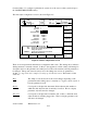
Device Configuration
Device
Used
Status
System 5000 Card Rack Yes
5000 High Speed Serial Bus Interface Yes
R/D-Brake Monitor Module No
Prog. Limit Switch (1-8) Yes
Prog. Limit Switch (9-16) Yes
Prog. Limit Switch (17-24) Yes
Prog. Limit Switch (25-32) Yes
Prog. Limit Switch (33-40) No
Prog. Limit Switch (41-48) No
Prog. Limit Switch (49-56 ) No
Prog. Limit Switch (57-64 ) No
Prog. Limit Switch (65-72) No
Prog. Limit Switch (73-80) No
Prog. Limit Switch (81-88 ) No
Prog. Limit Switch (89-96 ) No
Die Protection Mod. 1 No
Die Protection Mod. 2 No
Die Protection Mod. 3 No
Die Protection Mod. 4 No
Die Protection Mod. 5 No
Stroke
Mode
DEVICE
CONFIG
UPDATE
PROGRAM
0
0
TOP
EXIT
PC STATUS
Program/Run Switch
Stroke
Speed
MM
SPM
304.8
0
LAST STOP
Auto Stop on Top
Dist To
BDC
Local
Single Stroke
TOGGLE
USE
DEVICE
INFO
DIAGNOSTIC
COUNTERS
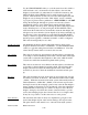
Device Configuration
Device
Used
Status
Auto Setups Mod. 2 No
Auto Setups Mod. 3 No
Auto Setups Mod. 4 No
NEXT PAGE
PREVIOUS
PAGE
Tonnage & Analog Signal Monitor YES
CONFIGURE
OPTION
OPTION
UPDATES
OPTION
UPDATES
Auto Setups Mod. 1
YES
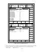
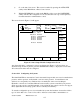
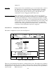
Figure 4-2 Device Configuration Screen
The left column of the Device Configuration screen lists hardware modules that can be used with
the system. The center column indicates whether the device is used with this particular