OmniLink II Press Automation Control Automatic Setup Module OPERATING MANUAL Version 1.
TABLE OF CONTENTS Section 1 Introduction.................................................................................................................. 1-1 Section 1.1 Counterbalance Control ............................................................................... 1-1 Section 1.2 Cushion Control ........................................................................................... 1-2 Section 1.3 Shut Height Control ..............................................................................
Section 4.2.2.2 Calibrating a Rotary Slide Adjust System ......................................... 4-13 Section 5 Operation...................................................................................................................... 5-1 Section 5.1 Slide Adjust Operation................................................................................. 5-3 Section 5.1.1 Slide On, Manual, and Off Settings ............................................................ 5-4 Section 5.1.
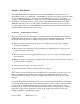
Section 1 Introduction The 5100-10 Automatic Setup Module allows the OmniLink II Press Automation Control to automatically adjust press shut height, counterbalance air pressure and cushion air pressure when jobs are recalled from memory. It consists of a base 5100-10 microprocessor board that connects to the OmniLink II Press Automation Control system, and additional boards that may be mounted on the base board to provide pressure or shut height adjustment functions.
Section 1.2 Cushion Control Quick die change is becoming increasingly important to maintaining a competitive edge. By controlling cushions pressure automatically, the Automatic Setup module can shorten die change and assure a correct setup in the least amount of time. Section 1.
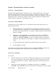
Section 2 Parameter Entry and Access Control Section 2.1 Parameter Entry Throughout the OmniLink II Press Automation control, a fairly standard form of data entry is employed. When data entry is allowed, an “editing cursor” will appear on the screen. This cursor can typically be moved from parameter to parameter on the screen with the up, down, left, and right arrow keys. The topmost softkey is used to select the parameter for editing and can change description depending on the parameter selected.
say “CHANGE TEXT” or “CHANGE DESC.” In any case, hit this softkey to enter text entry mode. The right-hand softkeys will change, a letter selection box will appear, and the editing cursor will change to a rectangle around the text to be edited. Figure 2.1 shows the softkeys and an example text parameter.
h) After the text has been changed as desired, press the ENT key to accept the changes. Section 2.2 Access Control The OmniLink control has several parameters or operations that have limited access. In regards to the auto setup module the ability to perform the actions of resetting faults or changing limits must be restricted to certain personnel. The OmniLink control provides several means to limit access to these parameters or operations. These parameters and operations are called restricted items.
the password the operator can reset auto setup faults. This is the only auto setup related item to which the operator has access. In order to load a die, the set-up personnel uses the RUN/PROG key to recall a job from job memory. The set-up personnel will also be able to make changes to auto setup parameters. Once the set-up personnel sets the die and verifies its correct operation, the operator is left to run the die.
Section 2.2.6 Access Control Operation To gain access control the user must use one of two means or a combination of these two means. These means are the RUN/PROG key or the user password system. Section 2.2.6.1 RUN/PROG Key Switch Operation The RUN/PROG key switch is located on the lower right side of the operator terminal. This is a two-position switch. The key is removable in the RUN position only.
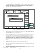
Order Counter 0 SPM 0 SPM PC STATUS READY TO STROKE Auto Setup PRESS SUPPLY ACCESS CODE KEY SUPPLY ACCESS CODE Slide Adjust #1 (ON) Setpoint: 20.000 in Actual Shutheight Fault: None Status: In Position 20.
After performing the steps listed above, the user will be logged in to the password system. The user will have access to all restricted items that have been designated for his access. This access will remain until the user performs a log out or until the user is automatically logged out. The user can log out by using the ACC key. This key will directly switch the display to the Quick Access screen. The “LOGOUT” soft key legend will appear along the bottom of the screen.
Section 3 Installation Section 3.1 Auto-Setup Module Installation The OmniLink II Press Automation Control Automatic Setup module can be used with the OmniLink II Press Automation Control system or with the OmniLink 5000 Press Control system. This is illustrated in Figure 3.1. The Automatic Setup module connects to either system via the high speed serial bus.
AUTO SETUP A S 1 S S 2 A S 2 A S 3 S S 1 A S 4 GND L1 NEU GND Figure 3-2 Faceplate Section 3.1.1 Module Assembly The OmniLink II Press Automation Control Automatic Setup module consists of a base board and optional plug-on boards. Each plug-on board can either add one slide adjust or two air adjust systems. For example if a system of one slide adjust and one counterbalance adjust is required, the slide adjust plug-on board should be installed in the SS1 slot.
After installing the plug-on boards to the base card and selecting the correct Module Number, slide the base card into the single slot card rack. The board slides into the two guides of the rack. It is held in place with two knurled screws at the top and bottom of the board. Section 3.1.3 Module Mounting The OmniLink II Press Automation Control Automatic Setup module can be mounted in the press control enclosure or it can be mounted in its own enclosure.
1. Input Power 2. High Speed Serial Bus Cable 3. Set High Speed Serial Bus Termination Switch Wiring of the slide adjust systems and air adjust systems will be described in the specific sections which describe their use and their connections. AUTO SETUP A S 1 S S 2 A S 2 A S 3 S S 1 A S 4 GND L1 NEU GND Figure 3-4 Primary Wiring and High Speed Bus Termination Section 3.1.4.1 Wiring Input Power Connection of AC input power is made to the 3 pin terminal block on the bottom of the module.
The 4 pin plug supplied for connection of the high speed serial bus is a dual connector plug. This dual connector plug allows for the high speed serial bus cable to be strung from module to module if an addition OmniLink II Press Automation module is to be connected from this unit. Section 3.1.4.3 Setting High Speed Serial Bus Termination Switch The high speed serial bus termination switch must be placed in the correct position. The high speed serial bus termination switch is labeled “Term. Switch”.
below a minimum value set by the manual regulator (as long as there is shop air pressure). This prevents cushion drift down when control power is off with its associated lost die pins below the press bolster and lost time while they are recovered. This valve also allows the cushions to be adjusted using the manual regulator path if the automatic system fails, allowing the press to be operated until the automatic system is restored.
Figure 3-7 Type "C" Valve Configuration Section 3.3 Counterbalance Control Installation The automatic counterbalance control system consists of an air control board mounted on the 5100 Automatic Setup base board, a control valve (or valves), and a pressure transducer. The typical manually controlled press counterbalance system looks something like Figure 3.8. Figure 3-8 Typical Counterbalance System For automatic control, the pressure regulator and check valve are replaced with an air valve system.
Figure 3-9 Auto-Counterbalance with Type “A” Integrated Valve Figure 3-10 Auto-Counterbalance with Type "C" Integrated Valve October 16, 2008 Manual Version 1.
Section 3.3.1 Counterbalance Pressure Transducer Mounting The system uses an automatic method of control in which the fill valve or dump valve is energized to raise or lower the pressure of the system and a pressure transducer is used to “tell” the Automatic Setup board the system pressure. The pressure transducer is constantly monitored to verify that the system is at the proper pressure. When filling or dumping air into or out of the counterbalance, the transducer tells the system when to stop.
Section 3.3.2 Counterbalance Air Valve System Mounting The mounting location of the valve system is not critical. Consideration should be given, however, to ease of maintenance, plumbing, and wiring when choosing the mounting location. Also note that sometimes the check valve in the original system may be up at the surge tank itself. The check valve in the original system must be removed for the automatic system to work properly. Section 3.3.3 Counterbalance System Wiring Refer to Appendix B, Figure B.
Figure 3-13 Cushion System with Type "B" Integrated Valve Section 3.4.1 Cushion Pressure Transducer Mounting The system uses a method of control in which the fill valve or dump valve is energized to raise or lower the pressure of the system. The pressure transducer tells the system when it has reached the proper pressure. Because air pressure drops occur across air lines when filling or dumping, proper placement of the pressure transducer is very important for correct operation of the system.
Figure 3-14 Acceptable Location for Mounting Cushion Pressure Transducer Section 3.4.2 Cushion Air Valve System Mounting The mounting location of the cushion air valve system is not critical. Consideration should be given, however, to ease of maintenance, plumbing, and wiring when choosing the mounting location. Also note that sometimes the check valve in the original system may be up at the surge tank itself. The check valve must be removed for the automatic system to work. Section 3.4.
slide adjust. Slide adjust motor(s) must be wired to the automatic shut height adjust board(s). In addition, a transducer must be mounted in such a way as to detect slide adjust position and wired to the automatic shut height board. Rotary transducers may be used when shafts that turn when shut height is adjusted are accessible such as a shaft that drives a mechanical shut height indicator. Section 3.5.
NOTE: The cable should remain unbroken except for the connector in this junction box to the shield integrity – do not splice the cable. Slide adjust motor starters with and without auxiliary contactors are supported. Solenoid air valves for air motors are also supported. Refer to Appendix B for typical wiring diagrams. Figures B.4 shows the wiring for an AMCI dual resolver. Figures B.5 and B.6 show the wiring of slide adjust motor starters with and without auxiliary contactors. Figure B.
Section 4 Configuration After the OmniLink II Press Automation Control Automatic Setup module is installed (see section 3.1), it must be configured to work with the press. Configuration consists of several steps that depend on the options selected for the module. This System Configuration is normally performed at start-up. It is usually not necessary to change the System Configuration unless devices are added or removed from the system.
device installation. The Device Configuration menu is also used to update the software in the various modules used with the system when needed or desired, although this normally will not need to be done when the system is initially configured. The OmniLink II Operator Terminal provides for the insertion of a smart media card with updated software to download to the various modules used with the system. Instructions for updating firmware will be included with the updated firmware.
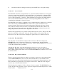
0 TOP 0 Stroke Mode Dist To BDC Local Stroke Single Stroke Speed 304.8 0 MM SPM LAST STOP Auto Stop on Top PC STATUS Program/Run Switch Device Configuration Used Device DEVICE CONFIG Status System 5000 Card Rack 5000 High Speed Serial Bus Interface R/D-Brake Monitor Module Yes Yes No TOGGLE USE Prog. Limit Switch (1-8) Prog. Limit Switch (9-16) Prog. Limit Switch (17-24) Prog. Limit Switch (25-32) Prog. Limit Switch (33-40) Prog. Limit Switch (41-48) Prog. Limit Switch (49-56 ) Prog.
OmniLink system. The right column is used to indicate information pertaining to device status, such as “detected”, which means the Operator Terminal has established communication with the module. The TOGGLE USED softkey will toggle the “Used” column for the highlighted (selected) device from No to Yes or Yes to No. The UPDATE PROGRAM softkey is used only in rare instances where it is desired to update software for a selected device to a newer version.
a) Go to the Auto Sets screen. This screen is reached by pressing the AUTO SETS softkey in the Main Menu or Press Control screen. b) With the RUN/PROG key switch in the PROG position, press the CONFIGURE softkey and enter the configuration code. Note that the code is provided separately from this manual for administrative control. The screen shown in Figure 4.3 will appear.
cushions. Slot AS5 controls hydraulic overloads. {Hydraulic Overload trip point control is currently unavailable}. In Figure 4.3, slot AS1 has already been assigned for control of a counterbalance. If it is necessary to add, change, or modify an Air Slot assignment, move the cursor to the Air Slot to be modified and press the CHANGE SETTING softkey. A list of available assignments for the Air Slot will appear. Move the cursor to the desired assignment and press the SELECT softkey.
parameter that the editing cursor is currently on. It gives a short version of how the parameter is used. Module Corresponds to the number of the Automatic Setups module that is currently being configured. Typical systems will have only one module. Up to four modules can be connected to one OmniLink II Press Automation Control or OmniLink 5000 Press Control. Air Slot Corresponds to the physical slot number (AS1 in the example of Figure 4.3) selected for configuration on the auto-setup card.
setting is 2. Fault Time If the pressure in the counterbalance goes out of tolerance due to a leak or any other reason, a countdown starts. The module will try to bring the pressure back into tolerance before the countdown expires. If it cannot correct the pressure, the press will be stopped. The fault time is the countdown in seconds. Suggested value is 20 seconds. Transducer Full Scale This value depends on the full scale rating of the pressure transducer being used.
be changed. The up and down arrow keys move the editing cursor from one parameter to another. See Appendix A for examples of setting up each kind of system. The features of this screen are: Help The “Help” box at the bottom of the screen changes depending on the parameter that the editing cursor is currently on. It gives a short version of how the parameter is used. Module Corresponds to the number of the Automatic Setups module that is currently being configured.
Type “B” and “C” valve systems may be used to provide a minimum pressure through their manual regulator. This keeps the cushion from falling due to air leakage when the control is powered off and prevents cushion pins from falling through the lower die shoe and bolster. NOTE! Cushions can always drift down when the plant air supply is off. Also, if a type “B” valve is used, Min Pressure must be set above the manual regulator setting.
tolerance limits. To configure a particular air system, move the cursor to that system and press the CONFIGURE SYSTEM softkey. The slide adjust configuration screen is shown in Figure 4.6.
Mode Use the CHANGE MODE softkey to cycle the status from ON to MAN to OFF and back to ON. ON means the module adjusts to the new shut height associated with a job when that job is recalled from memory, but only if the Slide Adjust OFF/ON selector switch is turned to the ON position. MAN means the module can control the shut height but the shut height can only be changed from the “Slide Adjust” screen or with the Jog-Up and Jog-Down remote pushbuttons.
make a preliminary stop slightly above the desired setpoint. The system will then incrementally “pulse” the slide adjust motor to achieve the desired slide setpoint position. The pulse distance value must be set by trial and error. A good starting point is .010" (.25mm). This value would turn off the slide adjust motor .010" (.25mm) above any setpoint entered before the pulse sequence would begin. The final stopping point will be less than .010" (.
IMPORTANT! Configuring/calibrating the slide adjust module should only be done with no dies installed in the press and, for presses equipped with slide counterbalance systems, should proceed only after the counterbalance is properly adjusted to offset the weight of the slide. If counterbalance pressure is too low, bearing clearances will cause shut height measurements made during calibration to be too small.
NOTE: e) It is very important make as accurate a measurement as possible for the Upper and Lower Calibration Points. If these measurements are wrong, then the slide position reported by the system will also be wrong! The system now needs an upper calibration point. With the press slide as near as possible to bottom dead center (180 degrees), use the JOG UP and JOG DOWN softkeys to take the slide near the top of the adjustment range.
Section 5 Operation The purpose of the Automatic Setup module is to allow automatic adjustment of such press systems as air counterbalances, air cushions, air operated hydraulic overloads, and slide adjust systems to greatly reduce setup time for different jobs, and to help ensure that these systems are adjusted correctly for different jobs.
b) Each configured sub-system has a status. Under normal conditions, this status will read “At Pressure” for air-based sub-systems such as counterbalances that are within the tolerance setting of the set pressure. Slide sub-systems will read “In Position” when within the tolerance setting for the shut height setpoint. See section 6 for an explanation of all status messages for the various sub-systems. c) Each configured sub-system has a fault message.
“CONFIGURE” Allows the individual options such as counterbalance, cushion, and slide adjust modules to be configured during initial installation of the system and will not be used for production operation setup. Note that this key is only available when the RUN/PROG keyed switch is in the PROG position. “JOG UP” Press this softkey to move the slide up. A momentary push will “pulse” the slide up once for fine control.
linear or rotary transducer mounted on the slide system of the press. The units for the position can be in inches or millimeters depending on the configuration. See section 4.2.2 for details. Fault If the slide adjust system detects an error it will be reported on this line. A fault occurs when a hardware or firmware problem is diagnosed by the system. See section 6 for fault messages and their meanings. Status The current status of the slide adjust system.
Section 5.1.2 Automatic Slide Movement Automatic movement of the slide can be initiated by either pressing the AUTO ADJUST” softkey in the slide adjust screen or when a stored job is recalled and the system is ON. Note that the AUTO ADJUST key will only appear when the slide adjust switch is ON. An auto adjust sequence always approaches the slide setpoint from above. For instance, if the current position is 10.000 and the slide setpoint is 12.000, the auto adjust sequence might take the slide first to 12.
IMPORTANT! Automatic movement will be terminated if the JOG UP softkey, JOG DOWN, or CANCEL AUTO ADJUST softkey is pressed while the slide is moving automatically. Automatic movement will pause if the slide adjust switch is turned off. It will resume when the slide adjust switch is turned back on. Section 5.1.3 Manual Slide Movement Manual slide movement can be controlled by the JOG UP and JOG DN softkeys or by the remote JOG UP and JOG DN pushbuttons. Section 5.1.3.
Section 5.2 Air System (Counterbalance, Cushion, and Hydraulic Overload Operation Counterbalances and cushions are all controlled by air pressure and as such are grouped as “air systems”. Each configured air system has its own “box” on the screen (see Figure 5.1). The title of the box has the air system name and the mode the system is in (ON, OFF, or MANUAL). This box contains: Pressure Set The desired pressure of the air system in psi.
reported on the top line after the air system name for operator information. The ON setting is the normal setting for each air system. The mode setting affects the air system in the following ways: “ON” Jobs that are recalled from memory will automatically take the air system to the pressure stored in the job. “MAN” (manual) The air pressure will not automatically change when a job is recalled. The pressure or force setpoint can still be changed by manually entering a desired pressure setpoint.
Section 5.2.4 Air System Fault and Status The last fault and current status of the air system are displayed for diagnostic and informational purposes. Under normal conditions the “Fault” message should be “None”. If there is a problem with an air system, it will be reported on the “Fault” line. “Status” gives the current state of the system such as “At Pressure”, “Filling”, “Dumping” etc. For the most part these messages will be self-explanatory.
Section 6 Diagnostics - Fault and Status Messages When the press control screen reports a stop condition that indicates the auto-setup board asserted or is asserting a stop signal, the “Auto-Sets” screen module status and the individual sub-systems status line will give additional information. Section 6.1 Main Module Messages OK General Module status is ok. This does not mean that the individual sub systems such as shut height control, counterbalance, and cushion control are ok.
Initializing Section 6.2 The Automatic Setup module is receiving its settings from the operator terminal. This message is normally seen only for a brief time. Counterbalance and Cushion “Fault” Messages None No error present Transducer Fail The pressure transducer gave a reading that is out of its normal range or gave no reading at all. Check that the transducer cable is still plugged in. If it is, check for cable damage. If the cable checks out the transducer may need to be replaced.
Section 6.3 Counterbalance and Cushion “Status” Message At Pressure The air system is within tolerance of its target pressure. Filling The system is filling (raising the air pressure). Dumping The system is dumping (lowering the air pressure). Pressure High The air pressure in the system is too high. Pressure Low The air pressure in the system is too low. System Off The system has been turned off in the configuration menu.
Down Relay Shorted The “Down” solid state relay on the slide adjust board failed shorted. Indicates a hardware failure of the relay. Lock Relay Open The “Lock” solid state relay on the slide adjust board failed open. Indicates a hardware failure of the relay. Lock Relay Shorted The “Lock” solid state relay on the slide adjust board failed shorted. Indicates a hardware failure of the relay. Transducer Fail The fine resolver on a rotary system could not be read correctly.
Sys not Detected Section 6.5 The hardware necessary for the system cannot be detected. For example if it was attempted to turn on a slide adjust system SS1 and a slide adjust system card was not installed in slot SS1, this error would appear. This could be either defective hardware or missing hardware. Slide Adjust “Status” Messages In Position The slide is within tolerance of the slide setpoint. Up Lim Switch The slide has hit the mechanical up limit switch and can go no higher.
Auto-Move Active The slide is automatically going to the programmed slide setpoint. Ext Jog Up The optional external jog up button is active. The slide should be moving up. Ext Jog Down The optional external jog down button is active. The slide should be moving down. Section 6.6 Slide Adjust Messages Calibration Only OK The slide adjust system calibration results are okay.
Coarse/Inc Turn Count Out of Synch The incremental turn count does not match the coarse resolver turn count. This could be caused by a bad connection or a hardware problem on the rotary circuit board (5100-10C). Rotary Transducer Read Failure The value read from the rotary transducer is invalid. This could be caused by a bad connection, a bad rotary transducer, or a hardware problem on the rotary circuit board (5100-10C).
Appendix A Configuration Examples This section of the manual will go though an example setup of each kind of system on a “typical” press. Each example assumes that the hardware installation has been completed and the system is ready for configuration. The following examples assume the access system is using “Key Only” mode as described in Section 2. Other modes may require entering a user code to change certain parameters. Section A.
Set the Min. Pressure to 25. Per the specifications listed this is the required pressure when there is no die attached to the upper ram. Set the Tolerance to 2 psi. Set the Fault Time to 20 seconds. Set the Transducer Full Scale to 200 psi. Per the specifications listed, the pressure transducer that we are using has a full scale rating of 200 psi. Finally, we go back to the Mode line and set the Mode to ON. See section 5.2 for operation details. Section A.
course this data can also be obtained from the cushion manufacturer. Set Min. Cushion Force to 0. Set the Max. Pressure to 90 psi. This is the maximum cushion pressure. Set the Min. Pressure to 2 psi. This is the value that just supports the weight of the cushion piston and pressure plate. Set the Tolerance to 2 psi. Set the Fault Time to 20 seconds. Set the Transducer Full Scale to 200 psi. Per the specifications listed, the pressure transducer that we are using has a full scale rating of 200 psi.
Set the Tolerance to .004 in. Set the Pulse Distance to .010 in. Set the Pulse Time to 30 msecs (milliseconds). Set the Resolver Turns to 100. A 100 turn dual resolver is being used to measure slide shut height. Before calibrating the slide, we MUST make sure the slide is properly counterbalanced, if a counterbalance is used on our press. If the slide is not properly counterbalanced, the slide calibration will be flawed because clearances will not be taken up by the counterbalance.
move .001 inch - an acceptable value. Now it is time to use the AUTO ADJUST softkey. Enter a setpoint slightly above the current reading. Assume that the current shut height reading is 13.800 inches. Enter a setpoint of 14.000 inches. Remember that the Slide Adjust OFF/ON selector switch should be in the ON position. Press the AUTO ADJUST softkey. The slide moves up past 14.000 (the slide setpoint we entered in the operation screen) and stops momentarily at 14.025. It then comes back down and stops at 13.
Appendix B Typical Wiring Diagrams AUTO SETUP A S 1 S S 2 A S 2 A S 3 S S 1 A S 4 GND L1 NEU GND Figure B.1 Typical Counterbalance Wiring Diagram October 16, 2008 Manual Version 1.
AUTO SETUP A S 1 S S 2 A S 2 A S 3 S S 1 A S 4 GND L1 NEU GND Figure B.2 Typical Cushion Wiring October 16, 2008 Manual Version 1.
Figure B.3 Conceptual Dual Resolver Mounting October 16, 2008 Manual Version 1.
AUTO SETUP A S 1 S S 2 A S 2 A S 3 S S 1 A S 4 GND L1 NEU GND Figure B.4 Typical AMCI Dual Resolver Wiring Diagram October 16, 2008 Manual Version 1.
Figure B.5 Typical Slide Motor Starter Wiring With Auxiliary Contactor Figure B.6 Typical Slide Motor Starter Wiring Without Auxiliary Contactor Figure B.7 Typical Slide Air Motor Solenoid Wiring October 16, 2008 Manual Version 1.
Figure B-8 Remote Jog Up and Jog Down Push Button Wiring October 16, 2008 Manual Version 1.
Appendix C Lockout Procedure For Air Controlled Systems Section C.1 General Lockout Considerations The OmniLink II Press Automation Automatic Setup module automatically controls pressures in cushions and counterbalances. Because of this there are special considerations to keep in mind when locking an air system out (at 0 pressure). Note that cushions can be vented to zero pressure and the press will be allowed to run.
Section C.3 Valve Type “B” Lockout Procedure The type “B” valve has a manual regulator in parallel with the automatic section that prevents the pressure it is controlling from going below a minimum. To lock this valve out: 1) Set the pressure setpoint for the air system to 0 psi. At this point the manual regulator will try to fill the system while the automatic section tries to dump. 2) Use the LOX valve (integrated into this type of valve) to dump the system and lock out the manual section.
Appendix D Specifications Section D.1 5100-10A Pressure Control Board AC Output Relays: Voltage: Current: Fuse: Section D.