Installation and Operating Manual LinkNet LinkNet Pressroom Monitoring Software
LinkNet Table of Contents 1. Introduction . . . . . . . . . . . . . . . . . . . . . . . . . . . . . . . . . . . . . . . . . . . . . . . . . . . . . . . . . . . . . . . . . . . . . . . 1.1 1.1 Features . . . . . . . . . . . . . . . . . . . . . . . . . . . . . . . . . . . . . . . . . . . . . . . . . . . . . . . . . . . . . . . . . . . . 1.1 1.2 System Requirements . . . . . . . . . . . . . . . . . . . . . . . . . . . . . . . . . . . . . . . . . . . . . . . . . . . . . . . . . . 1.1 2. Installation . . . . .
LinkNet 5. Reports . . . . . . . . . . . . . . . . . . . . . . . . . . . . . . . . . . . . . . . . . . . . . . . . . . . . . . . . . . . . . . . . . . . . . . . . . . 5.1 The Event Log Report . . . . . . . . . . . . . . . . . . . . . . . . . . . . . . . . . . . . . . . . . . . . . . . . . . . . . . . . . 5.2 The Summary Report . . . . . . . . . . . . . . . . . . . . . . . . . . . . . . . . . . . . . . . . . . . . . . . . . . . . . . . . . . 5.3 Press Performance Overview Report . . . . . . . . . . . . . . .
LinkNet etc. 1. Introduction d The Link Systems Network Application (LinkNet) provides detailed monitoring of stamping operations utilizing Link equipment. Supported equipment includes the OmniLink 5000 press control and associated option modules, and the System 1100 tonnage monitor. By using a simple to wire “daisy chained” cable arrangement to attach these units to an Intel based personal computer running Microsoft Windows, a wealth of information can be gathered automatically. 1.
LinkNet d At least one free RS232 serial port Recommended Hardware: d d d d d d Pentium II 333MHz CPU or better 32MB memory 4GB or larger hard drive SVGA (800 by 600) display or better Mouse At least one free RS232 serial port 1.2 manual rev 2.
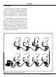
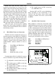
LinkNet 2. Installation LinkNet is connected to each piece of equipment in a bussed arrangement commonly called “daisy chaining”. The means that the communications cable goes from the computer to the first machine, from the first machine to the second, from the second to the third, and so on as shown in Figure 2.1. The “Drop Boxes” shown in the figure are small boxes that contain plugable terminal strips.
LinkNet At the computer, an RS232 to RS485 converter is necessary. This converts the standard serial port on the host computer to a differential serial port suitable for electrically noisy industrial environments. Link makes an RS232 to RS485 converter specifically for this purpose with termination resistors built in that provide for reliable communications. The computer that runs the network should be capable of running Windows 95, Windows 98, or Windows NT 4.0 (service pack 4 or higher).
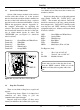
LinkNet Belden 8103 cable and many similar cables organized as twisted pairs use a special color code scheme. Instead of each wire using a different color, each pair uses a color. One wire in the pair is predominately white with a thin color stripe, and the other wire in the pair is predominately the color with a thin white stripe. When referring to these wires a common convention is to name the predominate color first.
LinkNet 2.3 System 1100 Connections System 1100 tonnage monitors with software versions older than version 3.2 in the operator interface board (the circuit board that is mounted on the door of the 1100) will need to have a software upgrade in order to function with LinkNet. Contact Link for the appropriate software. Appendix “A” has complete instructions for upgrading the software.
LinkNet 2.5 Figure 2.4: Regular Drop Box Connectors Software Installation Once the wiring is completed, the software on the host computer must be installed. Insert the LinkNet compact disk (CD) in the computers CDROM drive. If “Auto Insert Notification” is enabled for the drive (it is by default), then the LinkNet installation program will automatically start when the CD is inserted. If for some reason “Auto Insert Notification” is not enabled, hit the “Start” button on the desktop, select “Run...
LinkNet The installation program will create a new program group called “LinkNet” and will put a LinkNet icon on the windows desktop. To start LinkNet, double click on the icon on the desktop, or select it from the programs menu by hitting the Windows “Start” button, then “Programs”, then the “LinkNet” group, and then the “LinkNet” selection in that group. 2.6 manual rev 2.
LinkNet 3. Configuration After the software is installed, it must be configured. This consists of the following steps: d d Select a communications port for LinkNet to use to “talk” to the presses. Set the number, days, and starting times of shifts. Figure 3.1: Configuration Menu d Enter down time codes and their descriptions. d Tell LinkNet what machines are present. d Tell LinkNet what dies are present. d Configure Preventive maintenance. 3.1 Configuring the Comm Port Figure 3.
LinkNet same day or across days. If any shifts overlap in time, a message will be displayed indicating which days have a problem. 3.3 Figure 3.3: Shift Configuration Dialog Each day may have up to three shifts configured. The “Use This Shift” checkbox by each shift determines whether or not the shift will be used for that day. Note that a shift can be used some days and not others - each day is individually configurable.
LinkNet then be sent to each press on the network automatically. information in the database has been stored. If the DTC needs to be changed, delete the old DTC and add a new one with the desired number. 3.3.1 Adding a Down Time Code To Add a DTC, click on the “Add DTC” button. A dialog box similar to Figure 3.5 should appear. 3.3.3 Deleting a Down Time Code To delete a DTC, select a DTC from the list (see Figure 3.4) and click on the “Delete DTC” button.
LinkNet Figure 3.6: Machine Configuration List This dialog allows machine to be added, edited, and deleted. To add a machine, hit the “Add Machine” button. A dialog box like figure 3.7 will appear asking for the machine number of the machine to add. Figure 3.7: Machine Add Dialog Type the machine number and push the “OK” button. LinkNet will look for the machine on the network. If found, the dialog of Figure 3.8 will appear, otherwise a message indicating the machine could not be found will be displayed.
LinkNet Note that the idle condition will be activated ONLY if a down time code is not already entered and accounting for the lack of machine operation. A user entered down time code will always override the “Machine Idle” down time condition. “Standard Rate” is the expected average production rate in strokes per minute of this press. This value is used only if a standard rate is not entered for a machine/die combination. The standard rate value is used to compute machine utilization.
LinkNet can be changed on a machine by machine basis. Figure 3.10: Die Configuration Information Enter the machine number that this die information applies to, the die number, the die description, and the standard rate. The standard rate is used for press utilization calculations and is the strokes per minute, on average, that the die is expected to run on this press. This value can be different for each press the die will run on.
LinkNet Note that even if a job has been stored, settings associated with the Press Control, Die Protection, Tonnage Monitor, Programmable Limit Switch, Auto-Setup Board, Speed Control, and other specific press related settings which can affect machine/tool protection and/or operator safety can only be modified at the machine. This allows setup personnel to test and verify the configuration at the machine where they can see what effect changes have on the production process.
LinkNet engagements. PM can be set by machine or die. If set up by die, the PM settings will be tracked regardless of which machine the die is run on. For example, if a stroke based PM setting is applied to a die with a limit of 20000 strokes, then 10000 strokes run on machine 1234 and 10000 strokes run on machine 1100 will cause the limit to be reached. The actual configuration by machine or by die is identical except that dies have a default PM item “Strokes”.
LinkNet anything desired. Hit the “Add PM Item” button and the dialog of figure 3.15 should be displayed. d d d d Figure 3.15: PM Item Configuration The dialog of figure 3.15 shows the data already entered. The information to enter is as follows: d d PM Type - Select the type of limit this PM item should have. This can be one of the following: d Running Time - Amount of time the press was actually stroking since the last time this PM item was reset.
LinkNet 3.7.3 Resetting a Preventive Maintenance Item When a PM has “tripped” (exceeded its limit), it will appear in the “tripped items” PM report. When the item has been inspected or serviced, it must be reset for the next interval. Resetting the item leaves all the information the same except the value, which is reset to zero. The PM history report will show all the times and at what point this item has been reset.
LinkNet 4. Using LinkNet 4.1 The Overview Window When LinkNet is started, there is one screen open by default, the pressroom overview window (see Figure 4.1). This window contains information to give an “at a glance” status of the entire pressroom operation. Each column contains a different kind of information as follows: Mach # - The machine number of the press. This is the machine number that was programmed into the Link equipment on the press (see section 3.4).
LinkNet minute poll is multiplied by the remaining parts to be produced as given by the part counter to get an estimated completion time. Note that if the part counter is turned off or the average production rate is 0, this field will display “?:??” because there is not enough information to calculate a completion time. If the last 10 minute poll production rate is 0, the 15 second average strokes per minute is used instead.
LinkNet Tuesday. The average tonnage, highest good tonnage, and lowest good tonnage are collected in 10 minute intervals (unless a job is changed, in which case the interval is terminated to keep the tonnages associated with the correct job). The highest good tonnage is the highest tonnage that did not exceed the high setpoint and the lowest good tonnage is the lowest tonnage that did not go below the low setpoint. The average tonnage is the average of all in-limit hits.
LinkNet 4.2.4 Tonnage Detail The tonnage detail screen (“Peak Tons” tab - see Figure 4.5) shows the tonnage, high setpoint, low setpoint, reverse setpoint, and any alarms for each channel of the tonnage monitor. In addition, the mode of the tonnage monitor (run/program/bypass) and whether reverse and low limits are on or off are displayed on this screen. Notice that the bottom of the window menu lists all the windows that are open in LinkNet. The active window is the one with a check mark beside it.
LinkNet 5. Reports There are several reports that can be generated from the data that LinkNet collects. In addition, these reports can be modified by the user using a commercial software package called Crystal Reports available from Seagate Software. Many of these reports can be generated by machine or by die. To generate a report, select the “Report” menu. Reports can be generated by press as shown in figure 5.1, by die as shown in figure 5.2, or for preventive maintenance as shown in figure 5.3.
LinkNet The event log is captured by day because of the level of detail. This allows for keeping only certain days, if desired, to keep disk space requirements low.
LinkNet through, exported, or printed from the tool buttons at the top of the report window. The three sections in this report are: specific down time code breakdown, down time code category break down, and a machine utilization breakdown. The specific down time code breakdown section lists each different down time code with the number of occurrences, the total time, average time per occurrence, and percent of total time spent in that down time code.
LinkNet The graph shows the average tonnage, highest good tonnage, and lowest good tonnage which are collected in 10 minute intervals (unless a job is changed, in which case the interval is terminated to keep the tonnages associated with the correct job). The highest good tonnage is the highest tonnage that did not exceed the high setpoint and the lowest good tonnage is the lowest tonnage that did not go below the low setpoint of the tonnage monitor. The average tonnage is the average of all in-limit hits.
LinkNet d d d d d d 5.7 Number of presses the die ran on in this time interval. Standard SPM (strokes per minute) for the die. Actual SPM the die ran, on average. SPM variance between standard and actual. Die utilization percentage. Die uptime percentage. Die Tonnage Alarms Report The die tonnage alarm report shows how many and what kind of tonnage alarms a die has experienced in a given time frame.
LinkNet 6. Using the OmniLink 5000 with LinkNet The OmniLink 5000 press automation control gains some powerful new capabilities when combined with LinkNet. The OmniLink 5000 will work the same way it always has, but with a few additional screens and softkeys. 6.1 Configuring the OmniLink 5000 for LinkNet d d Hit the “CONFIG TASK” softkey and a screen similar to Figure 6.4 should appear. Highlight the field for “Machine Number” and enter the machine number desired for this press.
LinkNet Note that the “NETWORK OPS” softkey and the “Current DTC” message in the counter screen will not appear unless the Link Network has been configured as explained in section 6.1! To select or clear a DTC, hit the “NETWORK OPS” softkey in the counter screen. This will bring up a screen similar to Figure 6.5. Note that the down time code descriptions are the ones that are configured in LinkNet and downloaded to the OmniLink 5000 automatically. Figure 6.
LinkNet If a down time code is active, whether automatic or operator entered, a “CLEAR DTC” softkey will be displayed. Hitting this softkey or hitting the “CLR” key on the regular key pad will clear the down time code. 6.3 IMPORTANT! Jobs stored using the “STORE SETUP” softkey will still be stored as local jobs on the OmniLink as they always have - NOT the network. A job stored on the network is independent of the same job number stored at the OmniLink.
LinkNet 6.5 d Sending Tonnage Graphs from the OmniLink 5000 LinkNet has the ability to receive and display tonnage signatures from the OmniLink 5000 tonnage monitor. To send a tonnage signature to LinkNet, take the following steps: d d d d d From the main menu of the OmniLink OIT, hit the “TONNAGE MONITOR” softkey to enter the tonnage monitor main screen. Hit the “ARCHIVE WAVE” to send the waveform to LinkNet for storage in the waveform database.
LinkNet notes above. Hit the “MACHINE NOTES” softkey to view the machine notes again. 6.5 manual rev 2.
LinkNet 1100 Tonnage Monitor 7. Using the System 1100 Tonnage Monitor with LinkNet The System 1100 tonnage monitor gains down time codes, tonnage logging, and virtually unlimited job storage with the addition of LinkNet. The unit will operate as it always has, but will have an additional menu selection in the main menu called “NETWORK”. This menu will allow the operator to store and recall network jobs, view the network clock, and send tonnage graphs to the network.
LinkNet When a user entered DTC (not an automatic DTC) is active, the bar graphs beside each channel blink on and off to remind the operator that the DTC is in effect. In addition, the production counters (part, batch, and quality) do NOT count and average tonnage is not collected since the machine is not considered to be in production! Note that the “NETWORK” menu will not appear if LinkNet is not running, if the System 1100 has been not been properly configured as explained in section 7.
LinkNet 7.4 Network Job Recall on the System 1100 By using LinkNet, virtually unlimited job memory is available. Jobs can still be stored and recalled locally (in the System 1100) as they always have. When LinkNet is active, a new top level menu (the menu that is active when the 1100 is first powered up) called “NETWORK” becomes available. Note that the “NETWORK” menu will not appear if LinkNet is not running, if the System 1100 has been not been properly configured as explained in section 7.
LinkNet d Use the up and down arrow keys to select “CLOCK” and hit the “ENTER” key. A screen with the current time as transmitted from the host computer will be displayed. 7.4 manual rev 2.
LinkNet Appendix A - Upgrading Link Equipment Many new Link products will ship with network support - but products produced before September of 1998 may need to have software and/or hardware upgrades. New equipment may also need software upgrades to take advantage of new features both network and non-network related - it’s a good idea to check with Link on the status of any new software upgrades when installing the Link network. The following sections explain how to do the software and hardware upgrades.
LinkNet motherboard will prevent the unit from working correctly! d d d Install the Channel 1 and 2 dual channel card Be sure not to leave any lockwashers or screws loose in the unit! Restore power to the System 1100. Make sure that the System 1100 resets. You should see a screen that look similar to: LINK SYSTEMS 1100 V2.7 OIT V2.5MB on the LCD for about 5 seconds after power-up. The main menu should then appear. Figure A.1: System 1100 OIT Circuit Board A.2.
LinkNet A.3 OmniLink 5000 Upgrade Procedure Most OmniLink 5000 press controls shipped prior to July 1998 will need to have a hardware upgrade to work with LinkNet. This upgrade consists of replacing the old back plate and communications card on the operator interface terminal with a new back plate and communications card. To determine which kind of communications board is installed, look at the back of the OmniLink operator interface terminal (the box with the display screen on it - also called the OIT).
LinkNet Figure A.6: Figure A.5: OIT to New Communications Board Connections A.3.2 OmniLink Procedure d d d d d d OIT Circuit Board OIT Software Upgrade Review the chip changing rules in section A.1. Remove power from the OmniLink card rack and the OIT. Remove the screws from the back panel of the OIT, and remove the back panel. Using Figure A.6, locate and remove chips 5000-C, 5000-D, and 5000-E. Insert the new 5000-C, 5000-D, and 5000-E chips. Install the back panel on the Operator Terminal. A.
LinkNet A.3.3 OmniLink OIT Communications Card Software Upgrade Procedure A.3.4 OmniLink Procedure Logic Module Upgrade Note that older communications cards DO NOT have any software. This section applies ONLY to new communications cards. See Figures A.3 and A.4 to determine which card is present. The base card rack has only one card, the Logic Module, that contains software. To upgrade the logic module: d d d d d d d Review the chip changing rules of section A.1.
LinkNet A.3.5 OmniLink Die Protection Module Software Upgrade Procedure A.3.6 OmniLink Tonnage Monitor Module Software Upgrade Procedure This upgrade procedure applies only if the OmniLink control has an extended card rack and has the die protection module installed. This upgrade procedure applies only if the OmniLink control has an extended card rack and has the tonnage monitor module installed. d d d d d Review the chip changing rules of section A.1.
LinkNet A.3.7 OmniLink Auto-Setup Module Software Upgrade Procedure This upgrade procedure applies only if the OmniLink control has an extended card rack and has the auto-setup module installed. d d d d d Review the chip changing rules of section A.1. Remove power from the OmniLink card rack and the OIT. Remove the Auto-Setup board from the card rack. Remove the module (if present) installed in the SS1 position. Using Figure A.11, locate and remove the 500010 chip. Figure A.