Installation Instructions for the Lingenfelter TBRC-001 Temperature Based Relay Controller PN: L460220000 Revision - 1.0 Lingenfelter Performance Engineering 1557 Winchester Road Decatur, IN 46733 (260) 724-2552 (260) 724-8761 fax www.lingenfelter.
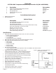
Parts List LPE TBRC-001 Temperature Based Ralay Controller Kit (PN: L460220000) # 1 1 2 2 6 • • Description TBRC-001 Temperature Based Relay Controller TBRC-001 pigtail harness, 36” Self tapping screws Hook and loop tape, per inch Instructions Phillips head screwdriver Wire crimping tool TBRC-001 XX04851-0003 AV16037 06483 N/A Tools & Materials Required Optional Items Description Two speed dual fan control harness with rela
Thank you for purchasing the Lingenfelter Performance Engineering (LPE) TBRC-001 Temperature Based Relay Controller. The TBRC-001 is designed to control two independent relays based on temperature sensor readings. This module can be used to: • • • Independently activate two relays in order to control fans, pumps, or other devices.
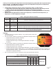
• Four (4) DIP switches for activating and controlling Output Cycling Mode • Output Cycling Mode is used in applications where the temperature sensor is not in the device that we are trying to measure, but instead in-line with the device. See the Output Cycling Mode section of the instructions on page 4 for further explanation of function and settings. • DIP switches #1-4 are used to control this setting. DIP switch #5 is inactive and has no effect on the setting.
Additional notes / warnings: • Changes to the settings on the TBRC-001 must be done with the ignition off. • The switch positions are only read when the module is powered up. • Do NOT submerge the module in liquid or directly wash the unit with liquid of any type! The switches on the TBRC001 are sealed but are NOT rated for high pressure washing, use caution if power washing near the TBRC-001 module. Mount the module where it will not be exposed to constant water.
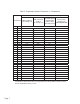
Troubleshooting If you believe that the TBRC-001 is switching at an incorrect temperature, check the following: • Use a multimeter to measure the sensor’s resistance at a certain temperature. Then, compare the resistance to the resistance values on the sensor type vs. sensor resistance chart on page 7. • Check to varify that you have set the 16 position (sensor type and hysteresis) switch to the correct range for your sensor type.
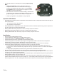
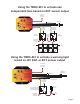
Using the TBRC-001 to activate two independent fans based on ECT sensor output To switched and fused 12v power TBRC-001 Temperature Based Relay Controller Temp2 x100 Temp2 x10 ECT Sensor To Ground Relay #2 On Temp +12V Switched Power - Red Ground - Black Sensor Ground - Brown Relay #1 On Temp Sensor Signal - Purple Temp1 x10 Relay Output #1 - Gray Relay Output #2 - Yellow Temp1 x100 To switched and fused 12v power Power 85 To switched and fused 12v power 30 85 Fan #2 Control Relay 30 Fan #1
Table 3: Temperature Sensor Resistance vs. Temperature Temperature sensor type (settings group on TBRC-001) Temperature GM ECT/IAT/TFT AEM / Autometer 1/8 NPT (use settings 0-3) (use settings 4-7) • Page 7.
1557 Winchester Road Decatur, Indiana 46733 (260) 724-2552 phone (260) 724-8761 fax www.lingenfelter.com L460220000 TBRC-001 temperature based relay controller v1.0.indd Page 8. N/A 213-4333 20907436 12458118 12608814 12614717 12160244 15936931 12636612 12146312 15326388 1795138 1924495 12110446 12146830 25036751 25037225 25037034 Differential Oil Cooler Temp. Sensor Manual TFT Sensor ECT Sensor IAT Sensor, fast response IAT Sensor, fast response Ambient Air Temp.