
User Manual

Page 6 of 12
Settings:
• Controlled by two (2) sixteen (16) position switches (as labeled on page 3 and on the module itself).
o One switch is for selecting the Function. The following functions (modes) exist at this time:
o The rst switch setting in each PPM group (setting 0, 4, 8 or C) enables the gear change
simulation function (Table A).
o The second switch setting in each PPM group (setting 1, 5, 9, or D) enables the low speed
range (Table B, Low (1)) MPH activated switch function.
o The third switch setting in each PPM group (setting 2, 6, A or E) enables the standard speed
range (Table B, Std (2)) MPH output switch function.
o The fourth switch setting in each PPM group (setting 3, 7, B or F) enables the high speed
range (Table B, High (3)) MPH output switch function.
o Second switch is for selecting the Range (within table A or B)
Notes:
• Changes to the MPH switch point settings must be done with the STOV powered off.
o The switch positions are only read on start up
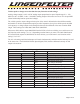
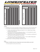
Table A
Speed (MPH)
Gear Change
1 2 3 4 5
Range Switch Position
0 0 30 60 110 140 175
1 1 25 50 95 125 155
2 2 20 45 90 115 140
3 3 20 40 80 105 130
4 4 40 75 120 175 220
5 5 35 70 115 170 210
6 6 30 65 105 150 200
7 7 55 80 110 140 190
8 8 50 75 100 130 175
9 9 45 70 95 125 165
10 A 40 65 90 120 160
11 B 47 80 123 164 200
12 C 44 75 116 154 190
13 D 38 65 100 133 180
14 E 35 60 92 122 166
15 F 32 55 85 113 152
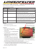
Table B
Switch Position
Speed in MPH (mode)
Low (1) Std (2) High (3)
Range Switch Position
0 OFF OFF OFF
1 1 10 110
2 2 20 120
3 3 30 130
4 4 40 140
5 5 50 150
6 6 60 160
7 7 70 170
8 8 80 180
9 9 90 190
A 10 100 200
B 11 110 210
C 12 120 220
D 13 130 230
E 14 140 240
F 15 150 250