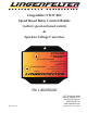
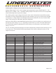
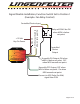
Lingenfelter STOV-002 Speed Based Relay Control Module (vehicle speed activated switch) & Speed to Voltage Convertor 5 4 3 6 2 7 8 9 1 0 F A B C D E STOV-002 Speed to Voltage Conv nve ertor Co Function Selection +12V Switched Power - Red 2 5 4 3 6 7 8 9 1 0 F A B C D E Ground - Black Range Selection Voltage Out - Yellow Stage Out / Norm On - Gray Activation Out / Norm Off - Green Power PPM Signal Input - White PN: L460050000 Revision 3.
Parts List # Part number 1 STOV-002 1 2 AV16037 1 L920010000 1 Description LPE MPH Activated Switch hook & loop tape self-tapping screw LPE decal instructions Optional Parts List Part Number Description 0334680003 E38/E67 ECM pin L450100000 Sealed 40 amp relay kit STOV-002 basic operation description: Input and output wires (see wiring table on page 5): The vehicle speed input signal to the STOV is Engine Control Module (ECM) or Powertrain Control Modul
Specifications: · The Lingenfelter Performance Engineering STOV-002 Speed To Voltage Convertor and MPH Activated Switch incorporates a precision 32-bit timer to realize microsecond precision over a very wide operating MPH range.
Stage/gear simulator Function output control mode (Function switch setting 0, 4, 8 or C depending on PPM output): This mode is used to provide a stage/gear shift simulated output for boost controllers and other devices that need to see a gear shift position switch output to change stages, such as: · AMS-1000 boost controller from NLR Systems · Innovative Turbo Systems MSBC01 Multi-Stage boost controller Operation as MPH increases - When the 1st table entry is reached the green wire “Activati
Vehicle speed to voltage conversion function (any Function switch setting): Analog voltage output is a 0-5 volt DC analog output proportional to speed. Speed range is 0 – 250 MPH (0 volts = 0 MPH, 5 volts = 250 MPH). Analog output will increase at a rate of .02 volt per MPH (linear relationship between speed and voltage).
See the table below for the Function switch settings in each PPM range. Wiring (also labeled on module): Wire Color Red Black Yellow Gray Green White Label +12V Switched Power Ground Voltage Out Notes Connects to a switched +12 volt source. Connects to a vehicle ground. This is the vehicle speed output voltage (analog voltage output). This is a 0-5 volt DC output. Stage Out / Norm On This is the first of two output wires.
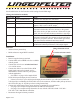
Table A Gear Change 1 2 3 4 5 Switch Position Speed in MPH (mode) Low (1) Std (2) High (3) OFF 0 0 30 60 110 140 175 0 OFF OFF 1 1 25 50 95 125 155 1 1 10 110 2 2 20 45 90 115 140 2 2 20 120 3 3 20 40 80 105 130 3 3 30 130 4 4 40 75 120 175 220 4 4 40 140 5 5 35 70 115 170 210 5 5 50 150 6 6 30 65 105 150 200 6 6 60 160 7 7 55 80 110 140 190 7 7 70 170 8 8 50 75 100 130 175 8 8 80 180 9 9 45 70 95
STOV-002 to AMS-1000 boost controller: The Stage input for the AMS-1000 can be configured for either ground or +12v. It can be pulsed input or an analog voltage input. To connect the STOV-002 to the AMS-1000 we recommend using analog voltage input setting and the analog voltage output from our MPH switch (Yellow voltage out wire). The voltage out data from the STOV-002 is not modified by any of the switch settings.
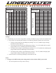
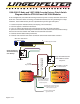
Signal Disable Installation, Function Switch Set to Position 1 (Example- Fan Relay Control) Controlled Device Input 5 4 3 6 2 7 8 9 1 0 F A B C D E STOV-002 Speed to Voltage Convertor Function Selection 0-5 Volt output based on MPH, .02 Volts per MPH +12 Volt Key-On Power Ground 85 30 86 87a 87 Relay will ONLY be ON when MPH is below set point.
1998-2002 F-Body and 1997-2008 Corvette Factory Clutch Switch Diagram with the STOV-002 and LNC-2000 Modules In this configuration, the STOV-002 is being used to only allow a 2-step controller to be active at the line. Once the vehicle is moving, the STOV-002 switches the relay, disabling the 2-step controller. Set the MPH switch point to a speed below your first gear shift point. 1 - Locate CPP (Clutch Position Switch) and unplug 2-wire connector. 2 - Cut wires appox. 3" back from connector.
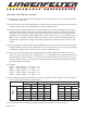
Table C ECM/PCM Speed Output Information for Common GM Vehicles Vehicle Year ECM/PCM Connector Pin Wire Color Circuit Number Camaro/Firebird 1996-1997 C2 (Black) 8 Dark Green/White 817 Camaro/Firebird 1998 C1 (Red) 55 Dark Green/White 817 Camaro/Firebird 1999-2002 C2 (Red) 50 Dark Green/White 817 Camaro 2010-2013 C1 (Black) 57 N/A N/A CK Truck 1999-2002 C2 (Red) 50 Dark Green/White 817 CK Truck 2003-2006 C2 (Green) 50 Dark Green/White 817 CK Truck 2007-2008* C1/X1
Retrieving VSS signal from vehicles that use CAN Bus: If the vehicle does not relay the VSS signal through the ECM/PCM connector (i.e. 2007-present CK Truck*, 2010-present Camaro, 2009-present CTS-V, etc...), you must enable the VSS signal in the ECM/ PCM, add a pin to the connector harness, and add a pull-up resistor. Most applications will require a pull-up resistor rated anywhere from 1-10 kΩ. LPE recommends using a 4.
For additional product installation information and technical support, contact LPE or your LPE products distributor. You can also find technical support and usage discussions regarding this product and many other LPE products in our Internet forums: http://www.lingenfelter.com/LPEforumfiles Follow us on Facebook! http://www.facebook.com/home.