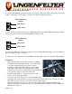
Installation Instructions For Lingenfelter Launch Control Module Adjustable Launch Controller & RPM Limiter For GM LSx Series Engines NOW With Timing Retard Mode PN: L460015297 1557 Winchester Road Decatur, Indiana 46733 260 724 2552 phone 260 724 8761 fax www.lingenfelter.
# 1 1 2 2 1 1 • • • • • • Part number LNC-001R AV16037 L920010000 Parts List Description LPE Launch Controller with timing retard function 48” trigger wire harness (part of PN LNC-001R) hook & loop tape, 3.
LNC-001R description: Sometimes referred to as a 2-step or launch controller, the LNC-001 can be used to provide consistent launch rpm off the line in drag racing and standing start road racing applications. In turbocharged applications the use of the LNC-001 also allows the engine to build more boost off the line during the launch. The LNC-001 can also be used as an adjustable individual cylinder rpm limiter, providing reliable and fast acting spark based engine rpm limit control.
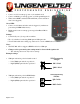
Red LED: • Comes on solid on start-up (power on) in standard mode • Comes on blinking on start-up (power on) in Programming mode • When active RPM is reached, LED will blink (even if activation wire is not triggered) Green LED: • Comes on solid when activation wire is triggered (on whenever powered up in RPM limiter mode) • Blinks retard count on start-up (power up) when Retard Mode enabled.
Programming Instructions IMPORTANT – If power is removed while in the process of changing operating modes the new settings may become corrupt. On power up the LNC-001 will check for valid settings and will default back to Normal Operating mode if an error has occurred. NOTE – The Operating Mode will only be changed if both Programming switches are set at 0 when power is applied.
Setting The Spark Timing Retard Value: 1 – Set the 100’s RPM programming switch to the desired setting. The actual setting will be the switch setting + 1. Example to set 5 degrees of retard you would set the 100’s switch to 4. RPM Programming Switches 901 456 23 100's Switch 78 9 01 456 23 1000's Switch 78 2 – Once you have set the desired degrees of Timing Retard move the 1000’s RPM programming switch to a non-zero position. At this time the Timing Retard setting is saved.
• • The only wiring that is required is for the trigger wire(s) depending on how you want to enable the device. See pages 7,8,9,10 & 11 for specific wiring diagrams. The possible connection methods are: • ground activation wire (green) - connect this wire to a source that supplies a ground path when you want the LNC-001 to become active • +12 volt activation wire (yellow) - connect this wire to a source that supplies +12 volts when you want the LNC-001 to become active (i.e.
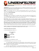
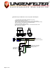
1998-2002 F-Body and 1998-2005 Corvette Factory Clutch Switch Diagram 1 - Locate CPP (Clutch Position Switch) and unplug 2-wire connector. 2 - Cut wires appox. 3" back from connector. 3 - Find +12 volt Key On power source and connect to one wire of CPP connector. 4 - Splice two wires onto remaining CPP connector wire and connect one wire to #85 on Relay. The extra wire will be used for LNC-001 Launch Controller activation. 5 - Connect terminal #86 on Relay to Ground.
Manual Transmission with Linelock 1 - Locate CPP (Clutch Position Switch) and unplug 2-wire connector. 2 - Cut wires appox. 3" back from connector. 3 - Find +12 volt Key On power source and connect to one wire of CPP connector. 1 4 - Splice two wires onto remaining CPP connector wire and connect one wire to #85 on Relay. The extra wire will be used for LNC-001 Launch Controller activation. 5 - Connect terminal #86 on Relay to Ground.
Manual Transmission with Linelock and Nitrous 1 - Locate CPP (Clutch Position Switch) and unplug 2-wire connector. 2 - Cut wires appox. 3" back from connector. 3 - Find +12 volt Key On power source and connect to one wire of CPP connector. 1 4 - Splice two wires onto remaining CPP connector wire and connect one wire to #85 on Relay. The extra wire will be used for LNC-001 Launch Controller activation. 5 - Connect terminal #86 on Relay to Ground.
Automatic Transmission with Linelock Optional LED, On when Arming Switch is ON.
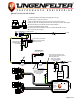
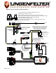
Automatic Transmission with Linelock and Nitrous The "Nitrous Disable Relay" is used to disconnect the "Wide Open Throttle" switch from the Nitrous Relay. This allows the throttle to go wide open while the Linelock / 2-Step is Active and the Nitrous will remain OFF until the Linelock is released. Wide Open Throttle Switch Nitrous Disable Relay. 85 30 C Cut WOT Switch wire and Install Relay as shown. Optional LED, On when Arming Switch is ON.
LNC-001 Wiring Diagram Female Male Male BOTTOM HOLES TOP HOLES Yellow Green Female ACT+ ACT- 20GA Jumper(s), 8" long.
Additional notes: Location of markings on case showing the date code and the letter code for the Timing Retard Function (“R”): It is the responsibility of the purchaser to follow all guidelines and safety procedures supplied with this product and any other manufactures product used with this product. It is also the responsibility of the purchaser to determine compatibility of this device with the vehicle and other components.