C5/C6 Corvette Clutch Return Spring Kit PN: L360080197 Revision - 1.1 Lingenfelter Performance Engineering 1557 Winchester Road Decatur, IN 46733 (260) 724-2552 (260) 724-0422 fax www.lingenfelter.
Parts List # 1 1 1 1 1 1 1 • • • • Clutch Return Spring and Bracket kit Description Corvette clutch return spring bracket, stainless Return spring, stainless w.
Read the entire instruction manual before beginning installation. Some stock parts will be used in reassembly. When referencing the side of the vehicle, the driver side of the vehicle is considered the left side and the passenger side of the vehicle is considered the right side of the vehicle. Multiple vehicles may be used for these installation instructions; however, the process remains the same for these applications.
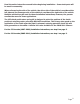
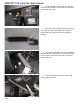
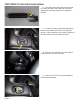
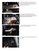
2005-2011 C6 Corvette Instructions 1. Locate the hole directly above the hood release lever located on the driver side foot well underneath the dash. 2. One side of the spring has a longer loop on it than the other. Insert the free end of the spring with the longer loop into the supplied bracket. 3. Insert the remaining free end of the spring with the shorter loop into the hole in the bracket on the vehicle and make sure that it is hooked around the hole. 4.
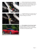
. Slide the bracket down to the machining tab on the clutch pedal as indicated by the red arrow. Insert the set screw and, using a 1/8” hex key, tighten it down to secure the clutch return spring bracket to the clutch pedal. 6. Install the locking nut on the end of the set screw. Using a 7/16” socket and torque wrench, torque the locking nut to 89 in-lb. 7. The installation of the clutch return spring kit is now complete on your C6 Corvette.
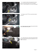
1997-2004 C5 Corvette Instructions 8. One side of the spring has a longer loop on it than the other. Insert the free end of the spring with the longer loop into the supplied bracket. 9. Locate your trunk release/fog light panel located on the bottom left side of your gauge cluster. Using a small pry tool, pop the panel out from the bottom of the instrument cluster. 10. Remove the connector from the back of the panel and set it off to the side. 11.
12. Locate the inside air temperature sensor panel on the bottom right side of your gauge cluster. Using a small pry tool, remove this panel. 13. Remove the T15 Torx screw from behind the panel. 14. Using a pry tool, remove the push clip from the left side of the kick panel. 15. Using a pry tool, remove the push clip from the right side of the kick panel located next to the OBD-2 connector. Page 6.
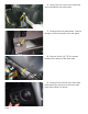
16. Using a pry tool, remove the metal push clip located above the clutch pedal. 17. Gently pull the kick panel down. Remove the light on the inner portion of the kick panel. 18. Remove the two (2) T15 Torx screws located on the bottom of the lower dash. 19. Gently pull the left side of the front dash panel toward you and remove the lower dash panel from behind it as shown. Page 7.
20. Disconnect the ambient inside temperature sensor from the lower dash panel. 21. Locate the 13mm bolt above and slightly in front of the hood release. There is a brace that holds the wiring harness to the frame. This must be removed to relocate the wires away from the spring on the clutch return spring bracket. 22. Locate the bolt on the frame that is indicated. There is a nut on top of the frame that must be loosend to allow the bolt to drop down.
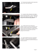
24. Make sure that there is no interference between the spring and the wiring harness. Using a 15mm wrench and socket socket, torque the dash frame bolt to 22 ft-lbs. 25. Move the wiring harness over to the right and secure it with the supplied cable tie as shown. This is to prevent the wiring harness from getting pinched between the spring. 26. Re-install the ambient inside temperature sensor in the lower dash panel. 27. Slide the lower dash panel behind the front dash panel. Page 9.
28. Re-install the two (2) T15 Torx bolts on the bottom of the lower dash panel. Torque both bolts to 89 in-lbs. 29. Push the metal push tab back into place. 30. Install the plastic push tab on the right of the kick panel back into place. 31. Install the plastic push tab on the left of the kick panel back into place. Page 10.
32. Re-install the T15 Torx screw on the ambient inside temperature sensor panel. Torque this bolt to 89 in-lb. 33. Re-install the plastic panel over the ambient inside temperature sensor. 34. Re-install the T15 Torx screw on the trunk release/fog light panel. Torque this bolt to 89 inlb. 35. Reconnect the trunk release/fog light electrical connector. Page 11.
36. Re-install the trunk release/fog light module. The installation of the clutch return spring kit is now complete on your Corvette. After driving the vehicle for a while we recommend checking the fasteners to make sure the bracket is still secured to the pedal assembly. Page 12.
For additional product installation information and technical support, contact LPE or your LPE products distributor. You can also find technical support and usage discussions regarding this product and many other LPE products in our Internet forums: http://www.lingenfelter.com/LPEforumfiles Follow us on Facebook! http://www.facebook.com/lingenfelter#!/lpehp Lingenfelter Performance Engineering 1557 Winchester Road Decatur, IN 46733 (260) 724-2552 (260) 724-0422 fax www.lingenfelter.