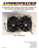
Lingenfelter High Capacity Intercooler Radiator for ZL1 Camaro and aftermarket supercharger equipped Camaro SS PN: L320061410 Revision - 1.0 Lingenfelter Performance Engineering 1557 Winchester Road Decatur, IN 46733 (260) 724-2552 (260) 724-8761 fax www.lingenfelter.
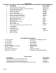
Parts List LPE Camaro SS and ZL1 Camaro High Capacity Intercooler Radiator Kit (PN:L320061410) # Description Part number 1 1 1 1 3 2 4 4 2 2 2 2 6 1 1 4 2 6 7 2 2 1 1 1 • • • • • • • • • Intercooler radiator and fan assembly Dual fan radiator wiring harness w relays and fuse holders Temperature based relay control Engine coolant temp sensor 15 amp fuse, ATC type 1/4” heat shrink, black 9/32” x 1 1/8” rubber grommet 5/16” x 1 1/4” stainless steel washer
The Lingenfelter Performance Engineering (LPE) High Capacity Intercooler Radiator is designed to improve the performance of the engine by reducing the charged air temperature at all RPM ranges and duty cycles. The system features a unique back to front double pass design to optimize heat transfer while maintaining the same flow rate through the charge air cooling system.
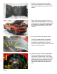
1. For the ZL1 Camaro remove the belly pan from the underside of the vehicle by removing the fourteen bolts using a 10 mm socket. 2. Raise and properly support the Camaro using a jack and jack stands, or a lift. Then remove the front two wheels and disconnect the ground from the battery. Please follow the GM lifting procedure for the 5th Gen Camaro 3. For a Camaro SS please skip to step 5. For a ZL1 Camaro remove five screws from the front bottom of the fender liner as marked.
. For ZL1 Camaro, please skip to step 6. On the Camaro SS remove the five screws using a 10 mm socket and the five fasteners using a flat head screw driver on the inner wheel well liner, then remove the wheel well liner. 6. Remove all six of the plastic retainer clips from the top of the front facia marked by yellow arrows using a flat head screwdriver. Using a 10 mm socket, loosen the two corner screws marked by the blue arrows. 7. Remove the bottom two screws of the front facia using a 10 mm socket.
9. Using a 10 mm wrench remove the 3 bolts on each side of the car that are in the top front area of the fender well. 10. Using a 10 mm socket, remove the bolt and screw on the side of the facia, accessed from the wheel well. Repeat on the other side of the car. 11. Finish Removing the corner screws on top of the front facia, and then carefully remove the front facia from the car and set it in a secure area to prevent accidental damage from occurring. 12.
13. For ZL1 convertibles, the front support brace has to be removed, using a 13mm socket, remove the four bolts holding it on. Note: This part will not be able to be reused with the Lingenfelter Intercooler. 14. Using a flat head screw driver, remove the eight plastic retainer clips marked in the picture and remove the plastic shrouds they are holding in. 15. Un-clip the air temperature sensor from the back of the passenger side plastic piece and finish removing the plastic piece. 16.
17. For Camaro SS please skip to step 20. Drain the intercooler by unscrewing the plug. Clamp the hoses off before the fittings to minimize mess and hassle. However, if the system is due for a flush, drain the full system by also unscrewing the cap that is under the plastic manifold cover on the supercharger. 18. Undo the hose clamps on the hoses that enter and exit the intercooler, remove the hoses from the intercooler and plug them with a 3/4” plug. 19.
21. Install the supplied coolant temperature sensor (PN:12608814) and tighten to 14 lb-ft (20 Nm) using a 3/4” wrench or deep socket. 22. Install the supplied intercooler radiator assembly (PN:XX05847-0002), place the washers on the bolts and using a 6mm Allen wrench, install the two top M8x1.25x20 stainless steel cap screw (PN:47543) loosely. Then using a 13mm socket and 6mm Allen wrench install the two side M8x1.
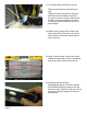
25. Turn the 90 degree fitting on the hose from the supercharger 90 degrees. Then connect the given section of hose. Route in desired location, trim the hose to length, and connect to the elbow at the top of the intercooler. 26. The plastic shrouds that were surrounding the stock intercooler must now be cut to fit the new Lingenfelter intercooler radiator. First start with the bottom air dam. Note: It is not recommended to just throw the plastic away.
29. Next is cutting the passenger side shroud, the one holding the air temperature sensor. Cut the part as shown here. Then sand the part to smooth out the edges, and round the lower corner by the mounting hole as shown by the arrow. 30. The cut the driver side shroud as shown. Then sand the part to smooth out the edges, and round the lower corner by the mounting hole as shown by the arrow. 31. Install the bottom air dam as shown, and push in the plastic retaining clips as marked. 32.
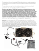
33. Lay the harness out over the intercooler, running the longer tail back into the engine bay from the passenger side, and the shorter end out over the intercooler to the drivers side. The relays should be positioned on the passenger side as close to the hood latch as possible. 34. With the harness laid out, connect the two fans to the harness. 35. Connect the intercooler coolant temperature sensor. 36. Route the wires in a suitable manner.
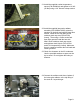
37. Once the wires are routed in a suitable position. Hold the relays up to the car and mark the centers of the holes in the brackets that hold the relays. Move the relays away, and using a punch make an indent where the hole is suppose to be. 38. Using a 3/16” drill bit, drill out the three holes, be careful not to drill through the back of the cross member. 39. Attach the relays using the supplied self tapping screws. 40. Remove the fuse and relay center cover. Page 12.
41. Run the long tail of the wiring harness, the part that is inside the engine bay, between the fuse block and fender. 42. Undo the power terminal using a 13mm socket, and connect the one red and two orange wires from the harness there. Put the nut back on the stud and torque it to 11 lb-ft (15 Nm). 43. Neatly route the wires so the TBRC-001 is beside the fuse block. 44. Using a 13mm wrench, undo the ground stud to the rear of the fuse block. Page 13.
45. Insert the three ground wires there, reinstall the bolt and tighten to 18 lb-ft (25 Nm). 46. Set the operating temperatures on the TBRC-001. Recommended temperatures are 90 degrees for fans on low and 110 for fans on high with a 10 degree hysteresis as shown in the picture to the left. Do this by turning the knobs for Temp 1 to 0 on the x100 and 9 on the x10; 1 on the x100 and 1 on the x10 for Temp 2 dials; and 1 on the 16 option dial. 47. Hold the TBRC-001 up to where you would like it mounted.
49. Stick one side of the hook and loop tape to the TBRC-001 and the other to the desired location on the car that was just cleaned. Place the TBRC-001 there so the two pieces of tape interlock. Attach the TBRC-001 using the supplied self tapping screws. Connect the TBRC-001 to the fan harness. 50. Fuse and relay center removal. Remove the fuse and relay block from its base by undoing the three bolts on the fuse block plate and the four tabs, two on each side.
53. Locate pin 15, the “Charge Air Coolant Pump B+” pin (circuit 2022). On some vehicles this will be a tan wire and others it will be a pink wire. 54. Mark the wire about an inch away from where it enters the fuse block. Pull the pin and wire out of the block, strip the coating away from the wire close to where it was just marked. Be careful to only cut the insulation itself and not the wire also. 55.
and insert the three bolts and make sure the four tabs on the perimeter are engaged. Tighten the three bolts to 89 lb-in (10 Nm). 58. If the optional manual override switch will not be installed, in order to maintain a water tight seal on the connectors, place the plug seals into the connector and close the retainer and connect it to the harness. 59.
three fuse holders. 62. Attach the fuse holders using the supplied self tapping screws. 63. Clip in the air temperature sensor. 64. Install the passenger side shroud. The top hole uses the factory plastic retainer clip while the lower hole is now held in by the side bolt on the intercooler. 65. Install the driver side shroud. The top is Page 18.
held in by the factory plastic retainer clip while the bottom is again held in by the side bolt from the intercooler. 66. Tighten down the side bolts and top bolts of the intercooler to 62 lb-in (7 Nm). 67. Fill the intercooler system with 50/50 Dex- Cool according to the GM fill procedure. Connect the battery and then run the car for short while and check for leaks.
four 10 mm head bolts to 89 lb-in (10 Nm). 70. Carefully place the front facia back onto the car, loosely install the corner screws on top of the facia. 71. Install the six bolts, three each side, on the sides of the facia, accessed from inside the wheel well and tighten to 62 lb-in (7 Nm). 72. Install the two 10 mm head bolts on the bottom of the facia and tighten to 62 lb-in (7 Nm). 73. Install the two bolts and two screws on the Page 20.
facia, one of each on each side accessed from inside the wheel well, and tighten the bolt to 27 lb-in (3 Nm) and the screw to 62 lb-in (7 Nm). 74. If the vehicle is equipped with fog lights, connect the fog lights harness to the facia. 75. Push in the six plastic retaining clips on top of the car and tighten down the two corner screws to 62 lb-in (7 Nm). 76. For the SS Camaro, please skip to step 79. For the ZL1 Camaro insert the fender liner. Start the seven screws in the wheel well to hold it in place.
of the facia and fender liner. 78. Install the five plastic retaining clips inside the wheel well and tighten the screws to 27 lb-in (3 Nm). Repeat on the other side. 79. For the ZL1 Camaro, please skip to step 81. For the SS Camaro insert the fender liner and start the five screws in the wheel well. 80. Install the plastic retaining clips and tighten the screws to 27 lb-in (3 Nm). Repeat on the other side. 81. For ZL1 Camaro’s, reinstall the belly pan, Page 22.
tightening the fourteen 10mm head bolts to 7 lb-ft (9 Nm). NOTE - if you are using jacks and jackstands to support/lift the car you may need to lower the vehicle first and then install the belly pan. 82. Install the wheels. Tighten the lug nuts. Lower the vehicle. Torque the lug nuts in a star pattern to 122 lb-ft (165 Nm). 83. Test the fans by setting the TBRC-001 to a lower than ambient temperature or by using jumpers in place of the relays. 84.
For additional product installation information and technical support, contact LPE or your LPE products distributor. You can also find technical support and usage discussions regarding this product and many other LPE products in our Internet forums: http://www.lingenfelter.com/LPEforumfiles Lingenfelter Performance Engineering 1557 Winchester Road Decatur, IN 46733 (260) 724-2552 (260) 724-8761 fax www.lingenfelter.com L320061410 Camaro Intercooler Radiator v1.1.indd Page 24.
Page
Page