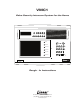
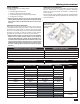
VMC1 Video Security Intercom System for the Home POWER 1 2 BAND 3 MEM ALARM DOWN 4 5 +5 UP ME-UP TUNER - VOLUME + AUX MUSIC RADIO FILTER 1 2 AUX 1 AUX 2 3 INPUT 5 6 7 VID 1 VID 2 VID 3 PRIV MON MUS CLEAR HOUSE DOOR 4 FILTER GATE STATUS LOCK AUX OUTPUT 1 AUX OUTPUT 2 Rough - In Instructions USA & Canada (800) 421-1587 & (800) 392-0123 (760) 438-7000 - Toll Free FAX (800) 468-1340 www.linearcorp.
IMPORTANT SAFETY INSTRUCTIONS SHOCK HAZARD CAUTION! This sign alerts user about un-insulated “dangerous voltage” that poses risk of electric shock. This sign warns user about important operating, maintenance, and servicing instructions for this product. Read Instructions - All safety and operating instructions should be read before installing or operating the VMC1 Video Intercom system. Retain Instructions - The safety and operating instructions should be retained for future reference.
IMPORTANT DO’S & DON’TS ✔ DO ensure that all instructions have been followed before power is applied to system. The installation shall be carried out in accordance with all applicable installation rules. ✔ DO use only Cat-5 & RG-6 and specified wires called out in these instructions. The cable is designed and constructed with electrical specifications necessary for proper audio performance. ✔ DO use only a damp cloth to clean the exterior plastics on the VMC1 Master Station and Room Stations.
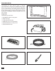
Table of Contents Block Diagram . . . . . . . . . . . . . . . . . . . . . . . . . . . . . . . . . . . . . . . . . . 3 Introduction. . . . . . . . . . . . . . . . . . . . . . . . . . . . . . . . . . . . . . . . . . . . 4 Rough-in Kit . . . . . . . . . . . . . . . . . . . . . . . . . . . . . . . . . . . . . . . . . . 4 Materials Required . . . . . . . . . . . . . . . . . . . . . . . . . . . . . . . . . . . . . . . . 5 Tools . . . . . . . . . . . . . . . . . . . . . . . . . . . . . . . . . . . . . . . . . . .
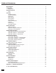
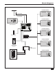
Block Diagram ROOM STATION - AM ANTENNA + VOLUME 4 1 2 3 5 6 7 PRIV MON MUS CLEAR HOUSE DOOR AUX FM ANTENNA ROOM STATION - DOOR STATION POWER 1 2 BAND 3 MEM ALARM DOWN 4 5 +5 + VOLUME 2 1 4 3 5 6 7 PRIV MON MUS CLEAR HOUSE DOOR AUX UP ME-UP TUNER - VOLUME + AUX MUSIC RADIO FILTER 1 2 AUX 1 AUX 2 5 6 3 INPUT 4 FILTER 7 GATE STATUS VID 1 VID 2 VID 3 PRIV MON MUS CLEAR HOUSE DOOR LOCK AUX OUTPUT 1 AUX OUTPUT 2 AUX MASTER STATION ROOM STAT
Introduction The VMC1H installation rough-in prepares the home to accommodate the video intercom system. A VMC1MB mounting bracket is necessary for the Master Station. Room stations and the Alloy Color Video Door Station (VMC1VDS) can be mounted directly onto finished walls. All other door stations require a rough-in enclosure (VMC1HR). The VMC1HR is also recommended for installing room stations in new construction or installations where the drywall has not yet been installed.
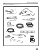
Materials Required Tools Most are required for purposes of this installation, but may vary according to installer preferences. WIRE STRIPPERS/CUTTER POWER DRILL WITH 1” AUGER 110 PUNCH-DOWN TOOL PHILLIPS SCREWDRIVER TAPE MEASURE 14/18 GAUGE WIRE CAT-5 CABLE COAX CABLE LEVEL MOUNTING SCREWS (VARIOUS SIZES) DRYWALL SAW 0-M 0.
Overview The VMC1 System Room Stations Designed for installation in new homes, the VMC1 is a Whole House Color Video Security Intercom system that provides room to room communication, multiple camera support, basic home automation controls, and video security for mid to large residential applications. VMC1 provide years of service and security for the homeowner as many people move into ‘smart home’ environment.
Wiring Information Cables and Wiring Cable Type and Configuration Excellent locations to run cables include: • Roof space • False ceilings/ bulkhead area • Through and/or around external walls • Under floors (subject to access being available) • Underground in conduit The general intercom functions for VMC1 can be cabled using Cat-5 or Cat-6 cables. If required, 6-conductor telephone cables can be used provided the system is configured for 6-wire operation.
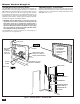
Master Station Rough-In VMC1MB Master Station Mounting Bracket VMC1MB Installation - Unfinished Wall The VMC1MB mounts flush with the wall stud and holds the Master Station and Power Supply (See Figure 1). Position the VMC1MB at a suggested height of 4-1/2 to 5-1/2 feet from the floor to center of the unit. As all wiring from other stations is generally terminated at the rear of the Master Station, the wall should be no less than 3 inches deep.
Master Station Rough-In VMC1MB Installation - Finished Wall Cut out an opening in the drywall (Height 7-1/4” x Width 11”) but do not cut right up against the wall stud. Allow 5/8” clearance between drywall opening and stud.This ensures that drywall will overlap bracket (See Figure 2). Slide the VMC1MB vertically, then turn clockwise 90˚. Mount in place onto stud using fasteners as shown. Hang Power Supply on VMC1MB in the lower right corner as shown.
Room Station Rough-In Room Station Mounting Room Station Installation - Finished Wall The Room Stations are normally mounted at a height from the floor of: 4-1/2’ to 5’. The Room Stations are not designed to be installed outdoors. Identify the location where the Room Station is to be installed. Cut a 3-1/2” x 7-3/4” rectangular hole in the drywall. When possible, one short edge should be situated against a wall stud to provide added support when installing the Room Station.
Door Station Rough-In VMC1VDS Door Station Rough-in The VMC1VDS is a metal door station with a 90 degree horizontal viewing area. It is normally mounted at a height from the floor of: 55” – 60”. When installing the VMC1VDS be aware of the camera location and the direction of sunlight and other ambient light. Direct sun or lighting into the lens of the VMC1VDS camera may impact the video quality. Additionally, exposure to extreme weather conditions is not recommended.
Door Station Rough-In VMC1HR Rough-in Enclosure VMC1VDS-S/BZ Door Station Rough-in The VMC1VDS-S and VMC1VDS-BZ incorporate a wide angle 120 degree horizontal viewing camera into a Door Station. It is normally mounted at a height from the floor of: 55” – 60”. Installation of this unit on an exterior wall requires 4 screws and anchors (See Figure 6). When installing these units, be aware of the camera location and the direction of sunlight and other ambient light.
Power Supply Rough-In TE6D Power Supply Power Supply Connections The Power Supply unit is pre-wired and self contained, and the wires are tucked inside. To access connection wires, open the Power Supply unit by removing four screws as shown in Figure 6. In the unlikely case that the TE6D electrical connectors become unplugged, the 3-pin and 6-pin connector blocks can be re-installed in their respective locations on the power supply board. Plug connectors in as shown.
Power Supply Rough-In Power Supply Wiring 1. Run a 14 AWG 120 VAC power cable (including ground) from a dedicated 15-amp circuit breaker to the Master Station Mounting Bracket location. The VMC1 requires a dedicated power source so there’s no interference from other equipment. 2. Route incoming power cable into the Power Supply enclosure through the hole on the SIDE of the Power Supply. 3. Use wire nuts to connect the incoming power cable to the TE6D Power Supply BLACK (HOT) and WHITE (NEUTRAL) input wires.
Data Hub Wiring H628 Data Hub The H628 Data Hub is used to connect each station to the Master Station. TIA-568A WIRING STANDARD Pull Wires Pull all the Door and Room Station cables to the location of the Master Station Mounting Bracket (VMC1MB). DATA HUB RJ-45 MODULAR PLUG If the installation consists of more than 5 room stations, Linear recommends using the optional Linear DMD-16 (16 stations) Data Distribution module and the Model H275 Universal Bracket (Optional, see Appendix A).
Antenna Installation Radio Antennas VMC1 requires two antennas, one for AM and one for FM reception. The AM antenna is a 25-foot wire the FM antenna is a 25-foot length of coax with a “T” shaped wire dipole at one end that attaches between rafters in the attic. ORIENTATE FM ANTENNA FOR STRONGEST RECEPTION Antenna arrangement is crucial to quality radio reception. AM and FM antennas should be placed at the highest point of the roof and at least six feet away from any electrical or intercom wiring.
Auxiliary Output Rough-In Door Release Rough-in Chime Activated Control Output Rough-In The Door Release Trigger can be activated from the VMC1 Master or any remote room station by pressing the Lock button. The Trigger will deactivate after 4 seconds and can be activated multiple times while the intercom is active. The Chime Activated Control Output allows for any number of security related automation functions including 10 available door chimes. To connect an auxiliary Chime refer to Figure 10.
Appendix A – Available Components System Master Station with 5.6” TFT LED color screen supporting up to 20 remote stations. Point-to-Point, Point-to-Group and All Call intercom with hands free response. UL 60950 certified VMC1 (White pictured) VMC1-BK (Black) VMC1-BZ (Bronze) Color Video Door Station with 10 different door chimes, 90º horizontal and 50º degree vertical viewing angle.
Appendix A – Available Components Starter Kit for VMC1 Security Intercom System one (1) Master, one (1) Alloy Door Station and four (4) room stations White(VMC1PACK) Non-video door station. Basic doorbell intercom station where video is not required. Standard weather resistance IP30 (VMC1DS-BZ Bronze) (VMC1DS-S Silver) pictured Nightstand station.
Appendix A – Available Components Mounting bracket for VMC1 Master Steel (VMC1MB) Rough in kit for the VMC1 Master.
Appendix A – Available Components Electronic Door Release w/power supplies Remote Door Lock (DRW) 12V Control Output switched 110V outlets for lights and other “notification” devices Remote Turn On for Lights AC1 (1 outlet) AC3 (2 outlets) MFG: Xantec/Niles 2-Channel Receiver (DXR-702) Miniature door / window transmitter (DXS-32) Wire Relay The 284 Leaded Accessory Relay is a 5 amp Form C relay with wire leads pre-attached.
2 - Year Limited Warranty Linear LLC warrants these products to be free of defects for 2 years. The warranty period begins on either (a) the date of purchase or installation date of this product or (b) the date of closing on a new residence in which this product was originally installed. The warranty extends to the original user of the product and to each subsequent owner of the product during the term of the warranty. Linear LLC will repair or replace, at its option, parts and materials at no charge.