PRINTER’S INSTRUCTIONS: INSTR,INSTL,AK-3 - LINEAR P/N: 221025 B - INK: BLACK - MATERIAL: 20 LB. MEAD BOND - SIZE: 8.500” X 11.000” - SCALE: 1-1 - FOLDING: ALBUM-FOLD - BINDING: SADDLE-STITCH AK-3 Digital Keyless Entry System 1 2 3 4 5 6 7 8 9 0 Installation and Programming Instructions (760) 438-7000 USA & Canada (800) 421-1587 & (800) 392-0123 Toll Free FAX (800) 468-1340 www.linearcorp.
CONTENTS COMPONENT LOCATIONS . . . . . . . . . . . . . . . . . . . . . . . . . . . . . . . . . . . . . . . WIRING DIAGRAM . . . . . . . . . . . . . . . . . . . . . . . . . . . . . . . . . . . . . . . . . . . INSTALLATION . . . . . . . . . . . . . . . . . . . . . . . . . . . . . . . . . . . . . . . . . . . . . . . Opening the Keypad . . . . . . . . . . . . . . . . . . . . . . . . . . . . . . . . . . . . . . . Install the Electrical Box and Mounting Plate . . . . . . . . . . . . . . . . . . . . . .
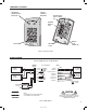
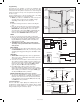
COMPONENT LOCATIONS RED/GREEN POWER/ACCESS INDICATOR YELLOW "LOCKOUT" INDICATOR MASTER CODE RESET JUMBER (P5) TERMINAL BLOCK #1 (TB1) 1 2 3 4 5 6 7 8 9 0 KEYPAD BEEPER LEVEL JUMPER (P4) MOUNTING PLATE Figure 1. Component Locations WIRING DIAGRAM TYPICAL DOOR INSTALLATION WIRING AK-3 TERMINALS TERMINAL BLOCK 1 1 - AC OR DC POWER SUPPLY 2 - AC OR DC 12-24 VOLT AC OR DC POWER 3 - N.O. MAIN RELAY 4 - COM 5 AMPS @ 28 VDC MAX. 5 - N.C. ELECTRIC DOOR STRIKE 6 - N.O.
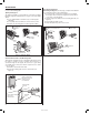
INSTALLATION Before installing the keypad, the unit must be partially disassembled to access the mounting plate. Opening the Keypad The keypad assembly is secured with two screws that are hidden behind the keypad’s nameplate. Refer to Figure 3 for disassembly details. ❑ Use a small flat blade screwdriver to pry off the keypad’s nameplate. ❑ Use a philips head screwdriver to remove the two screws. ❑ Separate the mounting plate from the keypad assembly.
Keypad Wiring See Figure 6 for an example of a basic door installation. The keypad is mounted adjacent to the door. An electric door strike is mounted in the door jamb to release the door lock. A magnetic switch is mounted on the top of the door jamb for detecting when the door is open. Use the following steps to wire the keypad. Refer to the wiring diagram shown in Figure 7 to assist in the wiring. ☞ NOTE: Up to 500 feet of 18 AWG wire can be run for power, use larger wire for longer runs.
FACTORY DEFAULTS Adding a New Entry Code MASTER PROGRAMMING CODE . . . . . . . . . . . . . . . . . . . . . . . . . . . . . . . . . . . . . . 123456 ENTRY CODE LENGTH . . . . . . . . . . . . . . . . . . . . . . . . . . . . . . . . . . . . . . . . . . . . . 4 DIGITS REQUEST-TO-EXIT OUTPUT RELAY . . . . . . . . . . . . . . . . . . . . . . . . . . . . . . . . . MAIN RELAY ALARM SHUNT OUTPUT . . . . . . . . . . . . . . . . . . . . . . . . . . . . . . . . . . . . . . . . . . DISABLED FORCED ENTRY OUTPUT . . . .
Program all normal entry codes to use the Main Relay (Relay #1), and only Relay #1 as the output relay. Program the code(s) that you want to use to hold the output for an indefinite period to the Auxiliary Relay (Relay #2). See the following example that sets entry codes 1234 for normal and 5678 for toggle operation. Select Keypad Active Output Default: No Output Sets which output activates when any keys are pressed. This output is timed.
Beep Sounds During Auxiliary Relay Default: No Selects whether or not the keypad beeps during Auxiliary Relay activation. Press: 4 2 # Sound # Sound = 1 for Yes, = 0 for No Beep Sounds During Output #3 Default: No Selects whether or not the keypad beeps during Output #3 activation. Press: 4 3 # Sound # Sound = 1 for Yes, = 0 for No Beep Sounds During Output #4 Default: No Selects whether or not the keypad beeps during Output #4 activation.