PRINTER’S INSTRUCTIONS: INSTR,INSTL,AE2000Plus - LINEAR P/N: 227541 B - INK: BLACK - MATERIAL: 20 LB. MEAD BOND - SIZE: 8.500” X 11.000” - SCALE: 1-1 - FOLDING: ALBUM-FOLD - BINDING: SADDLE-STITCH AE2000Plus Telephone Entry & Access Control System Installation Instructions USA & Canada (800) 421-1587 & (800) 392-0123 (760) 438-7000 - Toll Free FAX (800) 468-1340 www.linearcorp.
Contents Introduction ........................................................................... 2 Operation............................................................................... 2 Programming and Cardholder Maintenance............................ 2 Hardware Features ................................................................ 3 Software Highlights ............................................................... 3 Feature Overview ................................................................
Hardware Features ✓ BUILT-IN RADIO RECEIVER Variable gain, high-sensitivity receiver for wireless transmitters ✓ FOUR FORM “C” (N.O. & N.
Accessory Overview PBUS Accessories Several compatible accessories are available to connect to the three 6-wire communications “PBUS” inputs. Up to six PBUS accessories can be used with each AE2000Plus unit.
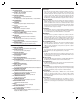
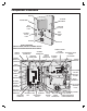
Component Locations DISPLAY OPTIONAL CAMERA MICROPHONE LEFT CABINET LOCK OPTIONAL POSTAL LOCK SPEAKER FUNCTION BUTTONS RIGHT CABINET LOCK KEYPAD INSTALLATION NOTE: FOR EASY WIRING, THE UNIT'S TERMINAL BLOCKS CAN BE UN-PLUGGED FROM THE CIRCUIT BOARD TAMPER SWITCH CAMERA CONNECTOR (HIDDEN) PROMPT SPEECH VOLUME ANTENNA CPU/INTERFACE RESIDENT'S VOICE ADJUSTMENT CONNECTOR CONNECTOR VOLUME TAMPER OPTIONAL RECEIVER ADJUSTMENT SWITCH RANGE KNOB CONNECTOR CAMERA TAMPER MAGNET VIDEO CONNECTOR WIEGAND INPUT TE
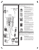
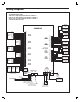
Wiring Diagram THIS WIRING EXAMPLE SHOWS: DOOR ACCESS WITH A DOOR STRIKE ON RELAY CHANNEL "A" DOOR ACCESS WITH A MAGNETIC LOCK ON RELAY CHANNEL "B" GATE ACCESS WITH A GATE OPERATOR ON RELAY CHANNEL "C" (YOUR INSTALLATION MAY VARY) ELECTRIC DOOR STRIKE AE2000PLUS PBUS DEVICE PWR GND DAT1 DAT0 DVAL PCLK PBUS DEVICE PBUS DEVICE NETWORK UNIT PWR GND DAT1 DAT0 DVAL PCLK PWR GND DAT1 DAT0 DVAL PCLK NETWORK UNIT NETWORK UNIT READER A TERMINALS LED2 HOLD LED1 DAT 1 DAT 0 GND PWR READER B TERMINALS PW
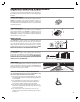
Important Mounting Requirements The AE2000Plus Telephone Entry System can be installed for public or private use. The mounting requirements will vary depending on the installation. Review the following information before beginning the installation. Mounting Environment Consider the environmental factors at the desired mounting location.
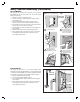
Entry System Mounting The AE2000Plus cabinet is designed to be mounted three ways: • The unit can be mounted directly to a wall or flat surface. • The unit can be mounted recessed into the wall. • The unit can be mounted on a standard gooseneck pedestal. Choose a well lit location near the controlled opening. Wiring access for power, telephone, earth ground, control output must be available to the mounting location.
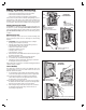
Entry System Mounting (Continued) Recessed Mounting The cabinet can be mounted recessed using the accessory trim-ring (P/N ACP00914). The trim-ring mounts in the wall and the cabinet attaches to the trim-ring. 1. Identify the location of any studs in the wall. 2. Cut a 15-½” wide by 19” high rectangular hole between studs at the mounting location. 3. Install any additional mounting material required to provide surfaces inside the wall 15-½” apart for attaching the trim-ring. 4.
Relay Output Wiring Door or Pedestrian Gate Control 1. Install a low voltage electric door strike or magnetic lock as a locking device for the door or pedestrian gate. 2. Install the power supply or transformer for the locking device. DO NOT POWER THE AE2000Plus FROM THIS POWER SUPPLY. 3. Connect one wire from the power supply to one wire from the locking device. 4. Route two wires between the locking device and the AE2000Plus. Connect one wire to the remaining wire of the locking device.
Power, Battery, & Ground Wiring Power Wiring ✦ NOTE: DO NOT APPLY POWER UNTIL THE INSTALLATION IS COMPLETE. TURN MASTER POWER SWITCH OFF BEFORE WIRING. 1. Route two wires between the AE2000Plus and the power transformer. • For power wire runs up to 75 feet, use 18 AWG, THHN 600-volt insulated wire. • For power wire runs up to 150 feet, use 16 AWG, THHN 600-volt insulated wire. 2. Connect the wires to the transformer. Connect the other end of the wires to the AE2000Plus AC1 & AC2 terminals.
Telephone Wiring For telephone entry and programming, the AE2000Plus connects to a standard telephone line. TELEPHONE TERMINALS Important Telephone Wiring Tips Typical Telephone Wiring 1A. If using the AE2000Plus modular connector for the telephone connection, connect a double-ended modular cable between the AE2000Plus PHONE jack and the modular telephone jack wired to the installation’s telephone line. 1B.
Optional Postal Lock A postal lock can be installed in the AE2000Plus Entry System to provide keyed access for the postal service. The AE2000Plus case is designed to accept a U.S. Postal Service postal lock. When the postal lock is engaged, the programmed output relay will activate. 2 REMOVE PLATE 1 REMOVE LOCKNUTS Postal Lock Installation 1. After opening the cabinet, re-lock the left cabinet lock to provide clearance to remove the postal lock switch plate. 2.
PBUS Accessories Up to six accessories (keypads, proximity readers, remote receivers) can be connected to the three PBUS input/output ports. A typical application for a remote keypad would be to control a second door or gate.
Optional Network Connections Linear’s AE1000Plus, AE2000Plus, & AM3Plus Access Control Systems can be connected together in a network. A network will allow sharing programming and user information between the systems. Program each unit to a different network Node Address (see Page 19). ✦ IMPORTANT COMPATIBILITY NOTE: Linear’s previous access control Models AE-1000, AE-2000, & AM3 can be used in networks with the Models AE1000Plus, AE2000Plus, & AM3Plus only using AccessBase2000 software.
Optional Network Connections (Continued) Network Configuration for AccessBase2000 Programming If the system is going to be programmed using Linear’s AccessBase2000 software, units communicate with each other on the network through RS-485 cable connections. AccessBase2000 does not support unit-to-unit network communications through modems, only RS-485 cable. AccessBase2000 does support modem communications from the PC to the eight Node #1 “master” units on an AccessBase2000 network.
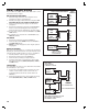
Optional Network Connections (Continued) RS-485 Network Wiring Network wiring conforms to 3-wire RS-485 electrical specifications. Units connected in the network can be wired using one unit as a “hub” or by wiring from one unit to the next in “daisy-chain” fashion. See the figures for wiring options. • Use Belden 9925 or Carol C0600 shielded cable or equivalent. Maximum wire run distance is 4000 feet. ✦ NOTE: Be sure to connect the cable’s shield to one of the GND terminals. Network Wiring with Hub 1.
System Adjustments The factory settings are sufficient for most installations. The system can be adjusted to customize the installation. SYSTEM VOLUME ADJUSTMENT LESS MORE System Volume Adjustment The sound level of the synthesized voice and key beep can be adjusted. 1. Locate the SYSTEM VOLUME adjustment on the CPU circuit board. 2. Press keys on the keypad while adjusting the control until the sound is at the desired level. Turn the adjustment clockwise for more volume, counterclockwise for less volume.
Internal Controls STATUS/PROGRAM DISPLAY On-board Pushbuttons "UP" BUTTON Seven pushbuttons are on the main circuit board. Refer to the figure for the location of each pushbutton. • UP button adds one to the value on the STATUS/PROGRAM display. • DOWN button subtracts one from value on the STATUS/PROGRAM display. Press with the UP button for one second to enter Programming Mode.
AE2000Plus Operation Resident Access with an Entry Code Visitor Access with a Resident Call PRESS THE KEY BELOW THE OR REPEATEDLY TO SCROLL THROUGH THE RESIDENT'S NAMES - OR - KEY IN AN ENTRY CODE AT THE SYSTEM KEYPAD OR ENTER A CODE AT A REMOTE KEYPAD TO SCROLL THROUGH FASTER, PRESS AND HOLD THE KEY BELOW OR THEN RELEASE THE KEY WHEN THE DESIRED LETTER IS UNDERLINED IF THE CODE IS ENTERED WRONG, PRESS THE KEY TO RESET THE KEYPAD AND RE-ENTER THE CORRECT CODE (USE THE KEY TO RESET REMOTE KEYPADS) WITH
Specifications MECHANICAL Case dimensions: ELECTRICAL Voltage: Current: Backup Battery: Outputs: 15-1/4” W x 19” H x 4” D 16-24 Volts AC or 12-24 Volts DC 2000 mA @ 16 VAC maximum Externally charged 12 Volt DC source, 6 amp/hr minimum Relay Channels A-D Form “C” 3 Amps @ 30 Volts maximum Inputs: Four normally closed door sense inputs Four normally open exit request inputs Two WIEGAND reader inputs Three PBUS inputs Network: Three-wire network RADIO Frequency: Bandwidth: Sensitivity: Encoding: ENVIRONMENT
Troubleshooting System completely dead 1. No power from transformer. Check voltage at transformer terminals. 2. Check voltage at AE2000Plus power terminal strip. Buzz on speaker 1. 2. 3. 4. 5. Check for 24 volt AC power shorted to wiring conduit. Check for telephone line shorted to ground. Verify that telephone wires are twisted pair. Verify that the AE2000Plus is connected to earth ground. Check 16 VAC voltage at AE2000Plus transformer terminals. Buzz on telephone line 1.
Linear Limited Warranty This Linear product is warranted against defects in material and workmanship for twenty-four (24) months. This warranty extends only to wholesale customers who buy direct from Linear or through Linear’s normal distribution channels. Linear does not warrant this product to consumers. Consumers should inquire from their selling dealer as to the nature of the dealer’s warranty, if any.
Copyright © 2008 Linear LLC 227541 B