
Datasheet


LTC4098/LTC4098-1
3
40981fc
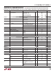
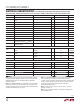
SYMBOL PARAMETER CONDITIONS MIN TYP MAX UNITS
I
VOUT
V
OUT
Current Available Before
Discharging Battery
1x Mode, BAT = 3.3V
5x Mode, BAT = 3.3V
10x Mode, BAT = 3.3V
Low Power Suspend Mode
High Power Suspend Mode
0.26
1.6
135
659
1231
0.32
2.04
0.41
2.46
mA
mA
mA
mA
mA
V
CLPROG
CLPROG Servo Voltage in Current Limit 1x, 5x, 10x Modes
Suspend Modes
1.188
100
V
mV
V
UVLO
V
BUS
Undervoltage Lockout Rising Threshold
Falling Threshold 3.95
4.30
4.00
4.35 V
V
V
DUVLO
V
BUS
to BAT Differential Undervoltage
Lockout
Rising Threshold
Falling Threshold
200
50
mV
mV
V
OUT
V
OUT
Voltage 1x, 5x, 10x Modes, 0V < BAT ≤ 4.2V,
I
VOUT
= 0mA, Battery Charger Off
3.5 BAT + 0.3 4.7 V
USB Suspend Modes, I
VOUT
= 250μA 4.5 4.6 4.7 V
f
OSC
Switching Frequency 1.96 2.25 2.65 MHz
R
PMOS
PMOS On-Resistance 0.18
Ω
R
NMOS
NMOS On-Resistance 0.30
Ω
I
PEAK
Peak Inductor Current Clamp 1x Mode
5x Mode
10x Mode
1.2
1.7
3
A
A
A
R
SUSP
Suspend LDO Output Resistance 15
Ω
Bat-Track External Switching Regulator Control
V
WALL
Absolute WALL Input Threshold Rising Threshold
Falling Threshold
4.2 4.3
3.2
4.4 V
V
ΔV
WALL
Differential WALL Input Threshold WALL-BAT Rising Threshold
WALL-BAT Falling Threshold 0
90
30 45
mV
mV
Regulation Target 3.5 BAT + 0.3 V
WALL Quiescent Current 100 μA
ACPR High Voltage I
ACPR
= 0mA V
OUT
V
ACPR Low Voltage I
ACPR
= 0mA 0 V
Overvoltage Protection
V
OVP
Overvoltage Protection Threshold Rising Threshold, R
OVSENS
= 6.04k 6.20 6.35 6.50 V
V
OVGATE
OVGATE Output Voltage Input Below V
OVP
Input Above V
OVP
1.88 • V
OVSENSE
0
12 V
V
t
RISE
OVGATE Time to Reach Regulation C
OVGATE
= 1nF 2.2 ms
Battery Charger
V
FLOAT
LTC4098 BAT Regulated Output Voltage
0°C ≤ T
A
≤ 85°C
4.179
4.165
4.200
4.200
4.221
4.235
V
V
LTC4098-1 BAT Regulated Output
Voltage 0°C ≤ T
A
≤ 85°C
4.080
4.066
4.100
4.100
4.121
4.134
V
V
I
CHG
Constant-Current Mode Charge Current R
PROG
= 1k, 10x Mode
R
PROG
= 5k, 5x, 10x Modes
980
192
1030
206
1080
220
mA
mA
I
BAT
Battery Drain Current V
BUS
> V
UVLO
, PowerPath Switching
Regulator On, Battery Charger Off,
I
VOUT
= 0μA
3.7 5 μA
V
BUS
= 0V, I
VOUT
= 0μA (Ideal Diode
Mode)
25 35 μA
ELECTRICAL CHARACTERISTICS
The l denotes the specifications which apply over the full operating
temperature range, otherwise specifications are at T
A
= 25°C. V
BUS
= 5V, BAT = 3.8V, R
CLPROG
= 3.01k, unless otherwise noted.