
Datasheet


LTC4098/LTC4098-1
24
40981fc
APPLICATIONS INFORMATION
R2R1
USB/WALL
ADAPTER
40981 F08
C1D1
MN1MP1
V
BUS
POSITIVE PROTECTION UP TO BVDSS OF MN1
V
BUS
NEGATIVE PROTECTION UP TO BVDSS OF MP1
V
BUS
OVSENS
OVGATE
LTC4098/
LTC4098-1
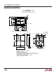
Figure 8. Dual-Polarity Voltage Protection
Reverse Voltage Protection
The
LTC4098/LTC4098-1
can also be easily protected
against the application of reverse voltage, as shown in
Figure 8. D1 and R1 are necessary to limit the maximum
VGS seen by MP1 during positive overvoltage events.
D1’s breakdown voltage must be safely below MP1’s
BVGS. The circuit shown in Figure 8 offers forward volt-
age protection up to MN1’s BVDSS and reverse voltage
protection up to MP1’s BVDSS.
Alternate NTC Thermistors and Biasing
The LTC4098/LTC4098-1 provide temperature-qualified
charging if a grounded thermistor and a bias resistor are
connected to NTC and NTCBIAS. By using a bias resistor
whose value is equal to the room temperature resistance
of the thermistor (R25) the upper and lower temperatures
are preprogrammed to approximately 40°C and 0°C, re-
spectively (assuming a Vishay curve 1 thermistor).
The upper and lower temperature thresholds can be ad-
justed by either a modification of the bias resistor value
or by adding a second adjustment resistor to the circuit.
If only the bias resistor is adjusted, then either the upper
or the lower threshold can be modified but not both. The
other trip point will be determined by the characteristics
of the thermistor. Using the bias resistor in addition to an
adjustment resistor, both the upper and the lower tempera-
ture trip points can be independently programmed with
the constraint that the difference between the upper and
lower temperature thresholds cannot decrease. Examples
of each technique are given below.
NTC thermistors have temperature characteristics which
are indicated on-resistance temperature conversion tables.
The Vishay-Dale thermistor NTHS0603N011-N1003F, used
in the following examples, has a nominal value of 100k
and follows the Vishay curve 1 resistance-temperature
characteristic.
In the explanation below, the following notation is used.
R25 = Value of the thermistor at 25°C
R
NTC|COLD
= Value of thermistor at the cold trip point
R
NTC|HOT
= Value of thermistor at the hot trip point
r
COLD
= Ratio of R
NTC|COLD
to R25
r
HOT
= Ratio of R
NTC|HOT
to R25
R
NOM
= Primary thermistor bias resistor (see Figure 9a)
R1 = Optional temperature range adjustment resistor
(see Figure 9b)
The trip points for the LTC4098/LTC4098-1’s temperature
qualification are internally programmed at 0.349 • NTCBIAS
for the hot threshold and 0.765 • NTCBIAS for the cold
threshold.
Therefore, the hot trip point is set when:
R
NTC|HOT
R
NOM
+R
NTC|HOT
•NTCBIAS = 0.349 •NTCBIAS
and the cold trip point is set when:
R
NTC|COLD
R
NOM
+R
NTC|COLD
•NTCBIAS = 0.765 •NTCBIAS
Solving these equations for R
NTC|COLD
and R
NTC|HOT
results in the following:
R
NTC|HOT
= 0.536 • R
NOM
and
R
NTC|COLD
= 3.25 • R
NOM
By setting R
NOM
equal to R25, the previous equations
result in r
HOT
= 0.536 and r
COLD
= 3.25. Referencing these
ratios to the Vishay Resistance-Temperature Curve 1 chart
gives a hot trip point of about 40°C and a cold trip point
of about 0°C. The difference between the hot and cold trip
points is approximately 40°C.