
Datasheet


LTC3861
8
3861fa
For more information www.linear.com/LTC3861
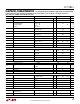
pin FuncTions
FB1 (Pin 1), FB2 (Pin 10): Error Amplifier Inverting Input.
Connect to VSNSOUT1, VNSOUT2 with a compensation
network for remote V
OUT
sensing. Connecting the FB to V
CC
disables the differential and error amplifiers of the respec-
tive channel, and will three-state the amplifier outputs.
COMP
1 (
Pin 2), COMP2 (Pin 9): Error Amplifier Outputs.
PWM duty cycle increases with this control voltage. The
error amplifiers in the LTC3861 are true operational ampli
-
fiers with low output impedance. As a result, the outputs
of
two active error amplifiers cannot be directly connected
together! For multiphase operation, connecting the FB pin
on an error amplifier to V
CC
will three-state the output of
that amplifier. Multiphase operation can then be achieved
by connecting all of the COMP pins together and using
one channel as the master and all others as slaves. When
the RUN pin is low, the respective COMP pin is actively
pulled down to ground.
VSNSP1 (Pin 3), VSNSP2 (Pin 8): Differential Sense
Amplifier Noninverting
Input. Connect this pin to the mid-
point of the feedback resistive divider between the positive
and negative output capacitor terminals.
VSNSN
1 (Pin 4), VSNSN2 (Pin 7): Differential Sense Am
-
plifier Inverting Input. Connect this pin to sense ground
at the output load.
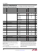
Typical perFormance characTerisTics
TRACK/SS Current
vs TRACK/SS Voltage
TRACK/SS Pull-Up Current
vs Temperature
RUN Threshold vs Temperature
RUN Pull-Up Current vs Temperature
TEMPERATURE (°C)
–50
RUN PIN VOLTAGE (V)
2.10
2.15
2.20
125
2.05
2.00
0 50
–25
25 75 100 150
1.95
1.90
2.25
3861 G28
RISING
FALLING
TEMPERATURE (°C)
–50
1.8
2.0
1.6
1.4
50
0
100 150
1.2
1.0
2.2
RUN PIN CURRENT (µA)
3861 G29
TRACK/SS PIN VOLTAGE (V)
0
TRACK/SS PIN CURRENT (µA)
–1.0
–0.5
0
–1.5
–2.0
2 4
1
3 5
–2.5
–3.0
0.5
3861 G30
TEMPERATURE (°C)
–50
2.2
TRACK/SS PIN CURRENT (µA)
2.4
2.6
2.8
0 50 150100
3.0
2.3
2.5
2.7
2.9
3861 G31