
Datasheet
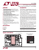


LTC3788
2
3788fc
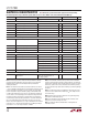
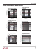
pin conFiguraTion
The l denotes the specifications which apply over the full operating
junction temperature range, otherwise specifications are at T
A
= 25°C, VBIAS = 12V, unless otherwise noted (Note 2).
absoluTe MaxiMuM raTings
VBIAS ........................................................ –0.3V to 40V
BOOST1, BOOST2 ...................................... –0.3V to 76V
SW1, SW2 .................................................. –0.3V to 70V
RUN1, RUN2 ................................................ –0.3V to 8V
Maximum Current Sourced into Pin
from Source > 8V .............................................100µA
PGOOD1, PGOOD2, PLLIN/MODE ............... –0.3V to 6V
INTV
CC
, (BOOST1-SW1, BOOST2-SW2) ...... –0.3V to 6V
EXTV
CC
........................................................ –0.3V to 6V
SENSE1
+
, SENSE1
–
,
SENSE2
+
, SENSE2
–
.................................... –0.3V to 40V
SENSE1
+
– SENSE1
–
,
SENSE2
+
– SENSE2
–
................................. –0.3V to 0.3V
I
LIM
, SS1, SS2, ITH1, ITH2, FREQ,
PHASMD, VFB1, VFB2 ...........................–0.3V to INTV
CC
Operating Junction Temperature Range ....–40°C to 125°C
Storage Temperature Range .................. –65°C to 125°C
(Notes 1, 3)
32
33
GND
31 30 29 28 27 26 25
9 10 11 12
TOP VIEW
UH PACKAGE
32-LEAD (5mm × 5mm) PLASTIC QFN
13 14 15 16
17
18
19
20
21
22
23
24
8
7
6
5
4
3
2
1SENSE1
–
FREQ
PHASMD
CLKOUT
PLLIN/MODE
SGND
RUN1
RUN2
BOOST1
BG1
VBIAS
PGND
EXTV
CC
INTV
CC
BG2
BOOST2
SENSE1
+
VFB1
ITH1
SS1
ILIM
PGOOD1
SW1
TG1
SENSE2
–
SENSE2
+
VFB2
ITH2
SS2
PGOOD2
SW2
TG2
T
JMAX
= 125°C, θ
JA
= 34°C/W
EXPOSED PAD (PIN 33) IS GND, MUST BE SOLDERED TO PCB
orDer inForMaTion
LEAD FREE FINISH TAPE AND REEL PART MARKING* PACKAGE DESCRIPTION TEMPERATURE RANGE
LTC3788EUH#PBF LTC3788EUH#TRPBF 3788
32-Lead (5mm × 5mm) Plastic QFN
–40°C to 125°C
LTC3788IUH#PBF LTC3788IUH#TRPBF 3788
32-Lead (5mm × 5mm) Plastic QFN
–40°C to 125°C
Consult LTC Marketing for parts specified with wider operating temperature ranges. *The temperature grade is identified by a label on the shipping container.
Consult LT C Marketing for information on non-standard lead based finish parts.
For more information on lead free part marking, go to: http://www.linear.com/leadfree/
For more information on tape and reel specifications, go to: http://www.linear.com/tapeandreel/
elecTrical characTerisTics
SYMBOL PARAMETER CONDITIONS MIN TYP MAX UNITS
Main Control Loop
VBIAS Chip Bias Voltage Operating Range 4.5 38 V
V
FB1,2
Regulated Feedback Voltage I
TH
= 1.2V (Note 4)
l
1.188 1.200 1.212 V
I
FB1,2
Feedback Current (Note 4) ±5 ±50 nA
V
REFLNREG
Reference Line Voltage Regulation VBIAS = 6V to 38V 0.002 0.02 %/V