
Datasheet


LTC3788
19
3788fc
applicaTions inForMaTion
The LTC3788 can also be configured as a 2-phase single
output converter where the outputs of the two channels
are connected together and both channels have the same
duty cycle. With 2-phase operation, the two channels of
the dual switching regulator are operated 180 degrees out-
of-phase. This effectively interleaves the output capacitor
current pulses, greatly reducing the output capacitor ripple
current. As a result, the ESR requirement of the capacitor
can be relaxed. Because the ripple current in the output
capacitor is a square wave, the ripple current requirements
for the output capacitor depend on the duty cycle, the num-
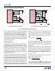
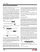
ber of phases and the maximum output current. Figure 3
illustrates the normalized output capacitor ripple current
as a function of duty cycle in a 2-phase configuration. To
choose a ripple current rating for the output capacitor,
first establish the duty cycle range based on the output
voltage and range of input voltage. Referring to Figure 3,
choose the worst-case high normalized ripple current as
a percentage of the maximum load current.
Multiple capacitors placed in parallel may be needed to
meet the ESR and RMS current handling requirements.
Dry tantalum, special polymer, aluminum electrolytic
and ceramic capacitors are all available in surface mount
packages.
Ceramic capacitors have excellent low ESR
characteristics but can have a high voltage coefficient.
Capacitors are now available with low ESR and high ripple
current ratings (i.e., OS-CON and POSCAP).
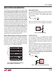
Setting Output Voltage
The LTC3788 output voltages are each set by an external
feedback resistor divider carefully placed across the out-
put, as shown in Figure 4. The regulated output voltage
is determined by:
V
OUT
= 1.2V 1+
R
B
R
A
Great care should be taken to route the V
FB
line away
from noise sources, such as the inductor or the SW line.
Figure 3. Normalized Output Capacitor Ripple
Current (RMS) for a Boost Converter
0.1
I
ORIPPLE
/I
OUT
0.9
3788 F03
0.3
0.5
0.7
0.8
0.2
0.4
0.6
3.25
3.00
2.75
2.50
2.25
2.00
1.75
1.50
1.25
1.00
0.75
0.50
0.25
0
DUTY CYCLE OR (1-V
IN
/V
OUT
)
1-PHASE
2-PHASE
Figure 4. Setting Output Voltage
LTC3788
VFB
V
OUT
R
B
R
A
3788 F04
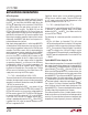
Figure 5. Using the SS Pin to Program Soft-Start
LTC3788
SS
C
SS
SGND
3788 F05
Soft-Start (SS Pins)
The start-up of each V
OUT
is controlled by the voltage
on the respective SS pins. When the voltage on the SS
pin is less than the internal 1.2V reference, the LTC3788
regulates the VFB pin voltage to the voltage on the SS pin
instead of 1.2V.
Soft-start is enabled by simply connecting a capacitor from
the SS pin to ground, as shown in Figure 5. An internal
10µA current source charges the capacitor, providing a
linear ramping voltage at the SS pin. The LTC3788 will
regulate the VFB pin (and hence, V
OUT
) according to the
voltage on the SS pin, allowing V
OUT
to rise smoothly
from V
IN
to its final regulated value. The total soft-start
time will be approximately:
t
SS
= C
SS
•
1.2V
10µA