
Datasheet


LTC3788
16
3788fc
applicaTions inForMaTion
always the same and varies with temperature. Consult
the manufacturer’s data sheets for detailed information.
Using the inductor ripple current value from the inductor
value calculation section, the target sense resistor value is:
R
SENSE(EQUIV)
=
V
SENSE(MAX)
I
MAX
+
∆I
L
2
To ensure that the application will deliver full load current
over the full operating temperature range, choose the
minimum value for the maximum current sense threshold
(V
SENSE(MAX)
).
Next, determine the DCR of the inductor. Where provided,
use the manufacturer’s maximum value, usually given at
20°C. Increase this value to account for the temperature
coefficient of resistance, which is approximately 0.4%/°C. A
conservative value for the maximum inductor temperature
(T
L(MAX)
) is 100°C.
To scale the maximum inductor DCR to the desired sense
resistor value, use the divider ratio:
R
D
=
R
SENSE(EQUIV)
DCR
MAX
at T
L(MAX)
C1 is usually selected to be in the range of 0.1µF to 0.47µF.
This forces R1|| R2 to around 2k, reducing error that might
have been caused by the SENSE
+
pin’s ±1µA current.
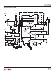
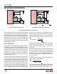
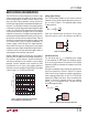
(2a) Using a Resistor to Sense Current (2b) Using the Inductor DCR to Sense Current
Figure 2. Tw o Different Methods of Sensing Current
TG
SW
BG
INDUCTOR
DCR
L
LTC3788
INTV
CC
BOOST
SENSE
+
SENSE
–
R2C1
R1
VBIAS
V
IN
V
OUT
PLACE C1 NEAR SENSE
PINS
SGND
3788 F02b
(R1
||
R2) • C1 =
L
DCR
R
SENSE(EQ)
= DCR •
R2
R1 + R2
TG
SW
BG
LTC3788
INTV
CC
BOOST
SENSE
+
SENSE
–
(OPTIONAL)
VBIAS
V
IN
V
OUT
SGND
3788 F02a
When using the controller in low V
IN
and very high voltage
output applications, the maximum output current level will
be reduced due to the internal compensation required to
meet stability criterion for boost regulators operating at
greater than 50% duty factor. A curve is provided in the
Typical Performance Characteristics section to estimate
this reduction in peak output current level depending upon
the operating duty factor.
Inductor DCR Sensing
For applications requiring the highest possible efficiency
at high load currents, the LTC3788 is capable of sensing
the voltage drop across the inductor DCR, as shown in
Figure 2b. The DCR of the inductor can be less than 1mΩ
for high current inductors. In a high current application
requiring such an inductor, conduction loss through a
sense resistor could reduce the efficiency by a few percent
compared to DCR sensing.
If the external R1||R2 • C1 time constant is chosen to be
exactly equal to the L/DCR time constant, the voltage drop
across the external capacitor is equal to the drop across
the inductor DCR multiplied by R2/(R1 + R2). R2 scales the
voltage across the sense terminals for applications where
the DCR is greater than the target sense resistor
value.
To properly
dimension the external filter components, the
DCR of the inductor must be known. It can be measured
using a good RLC meter, but the DCR tolerance is not