
Datasheet


LTC3230
9
3230fa
OPERATION
Power Management
The LTC3230 uses a switched capacitor charge pump to
boost CPO to as much as 2 times the input voltage up to
5V. The part starts up in 1x mode. In this mode, V
IN
is
connected directly to CPO. 1x mode provides maximum
effi ciency and minimum noise. The LTC3230 will remain in
1x mode until any LED current source drops out. Dropout
occurs when a current source voltage becomes too low
for the programmed current to be supplied. When dropout
is detected, the LTC3230 will switch into 1.5x mode. The
CPO voltage will then start to increase and will attempt to
reach 1.5x V
IN
up to 4.5V. Any subsequent dropout will
cause the part to enter 2x mode. The CPO voltage will
attempt to reach 2x V
IN
up to 5V. The part will be reset to
1x mode whenever the part is shut down or when either
ENM or ENS is driven low.
A 2-phase non-overlapping clock activates the charge pump
switches. In 2x mode the fl ying capacitors are charged on
alternate clock phases from V
IN
to minimize CPO voltage
ripple. In 1.5x mode the fl ying capacitors are charged in
series during the fi rst clock phase and stacked in parallel
on V
IN
during the second phase. This sequence of charg-
ing and discharging the fl ying capacitors continues at a
constant frequency of 900kHz.
LED Current Control
The MLED and SLED currents are delivered by program-
mable current sources controlled by the ENM and ENS
pins and by the value of the resistor on the R
SET
pin.
There are four MLED current sources controlled by the
ENM pin and one SLED current source controlled by the
ENS pin. Full-scale current in the MLED and SLED pins
are set by a resistor from the R
SET
pin to GND according
to the following formula:
MLED/SLED Full-Scale Output Current =
0.8
R
SETT
• 555
Thirty two linear current settings are available by applying
up to 31 pulses when enabling the ENM and ENS pins.
Each strobe counts down a 5-bit DAC to set the LED
current. When the desired count is reached, leave the
enable strobe high and the output current will be set to
the programmed value after a typical delay of 150μs. If
more than 31 strobes are received the counter will stop
at one LSB. The output current will be set to zero if the
enable is set low only after the 150μs delay. If the enable
is toggled before the 150μs delay, the DAC counter will
continue to count down and the current output will not be
enabled until the start-up delay is fi nished.
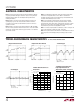
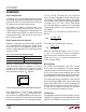
When both ENM and ENS are held low for more than
250μs (minimum) the LED drivers and charge pump will
go into shutdown. See Figure 1 for timing information. If
the charge pump is in either 1.5x or 2x modes, the falling
edge of either ENM or ENS will reset the charge pump to
1x mode.
PROGRAMMED
CURRENT
t
PWH
≥ 200ns
200ns < t
PWL
< 20μs
ENM OR ENS
LED
CURRENT
SHUTDOWN
t
EN
≥ 250μs t
SD
≥ 250μs
ENM = ENS = LOW
3230 F01
Figure 1. Current Programming Timing Diagram