
Datasheet


LTC3230
11
3230fa
OPERATION
charge pump function. Driving ENLDO1 and ENLDO2 high
enable LDO1 and LDO2 respectively. When the charge
pump is enabled, each LDO consumes an additional 60μA
(typical) from V
IN
. If the charge pump is not enabled, one
LDO consumes 125μA (typical) and the second uses 60μA
(typical) additional current.
LDO output voltage is set using three-level input pins V1
and V2 as shown in Table 2.
Table 2. LDO1 and LDO2 Output Voltage Control
V1 GND FLOAT V
IN
LDO1 (V) 1.2 1.5 1.8
V2 GND FLOAT V
IN
LDO2 (V) 1.8 2.8 3.3
The reference input to each LDO is ramped when enabled
to provide an output soft-start lasting typically 100μs.
When an LDO is disabled its output is pulled to ground
through an 11.5k resistor.
Shutdown Current
In shutdown mode all the circuitry is turned off and the
LTC3230 draws a very low current from the V
IN
supply.
When in shutdown, CPO is disconnected from V
IN
and is
pulled to ground through a 14.3k resistor. The LTC3230
enters shutdown mode when both ENM and ENS pins
are brought low for 250μs (minimum) and ENLDO1 and
ENLDO2 are brought low. All enable pins ENM, ENS, EN-
LDO1 and ENLDO2 have internal pull-downs to defi ne the
shutdown state whenever the inputs are fl oating.
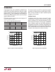
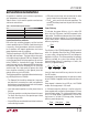
Figure 3. Typical 1.5x R
OL
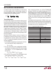
vs Temperature Figure 4. Typical 2x R
OL
vs Temperature
TEMPERATURE (°C)
–40
5
RESISTANCE (Ω)
6
7
8
9
10
11
–15 10 35 60
3230 G06
85
V
IN
= 3V
V
CPO
= 4.2V
C1 = C2 = C6 = 1μF
TEMPERATURE (°C)
–40
6
RESISTANCE (Ω)
7
8
9
10
11
12
–15 10 35 60
3230 G08
85
V
IN
= 3V
V
CPO
= 4.8V
C1 = C2 = C6 = 1μF