
Datasheet


LTC2990
14
Rev. F
For more information www.analog.com
APPLICATIONS INFORMATION
bit set to zero. The addressed LTC2990 acknowledges
the address and then the master sends a command byte
which indicates which internal register the master wishes
to write. The LTC2990 acknowledges the command byte
and then latches the lower four bits of the command byte
into its internal Register Address pointer. The master then
delivers the data byte and the LTC2990 acknowledges
once more and latches the data into its internal register.
The transmission is ended when the master sends a STOP
condition. If the master continues sending a second data
byte, as in a Write Word command, the second data byte
will be acknowledged by the LTC2990 and written to the
next register in sequence, if this register has write access.
Read Protocol
The master begins a read operation with a START condi-
tion followed by the seven bit slave address and the R/W#
bit set to zero. The addressed LTC2990 acknowledges
this and then the master sends a command byte which
indicates which internal register the master wishes to
read. The LTC2990 acknowledges this and then latches
the lower four bits of the command byte into its inter-
nal Register Address pointer. The master then sends a
repeated START condition followed by the same seven bit
address with the R/W# bit now set to one. The LTC2990
acknowledges and sends the contents of the requested
register. The transmission is ended when the master
sends a STOP condition. The register pointer is automati-
cally incremented after each byte is read. If the master
acknowledges the transmitted data byte, as in a Read
Word command, the LTC2990 will send the contents
of the next sequential register as the second data byte.
The byte following register 0x0F is register 0x00, or the
statusregister.
Control Register
The control register (Table5) determines the selected
measurement mode of the device. The LTC2990 can be
configured to measure voltages, currents and tempera-
tures. These measurements can be single-shot or repeated
measurements. Temperatures can be set to report in
Celsius or Kelvin temperature scales. The LTC2990 can
be configured to run particular measurements, or all pos-
sible measurements per the configuration specified by the
mode bits. The power-on default configuration of the con-
trol register is set to 0x00, which translates to a repeated
measurement of the internal temperature sensor, when
triggered. This mode prevents the application of remote
diode test currents on pins V1 and V3, and remote diode
terminations on pins V2 and V4 at power-up.
Status Register
The status register (Table4) reports the status of a par-
ticular conversion result. When new data is written into a
particular result register, the corresponding DATA_VALID
bit is set. When the register is addressed by the I
2
C inter-
face, the status bit (as well as the DATA_VALID bit in the
respective register) is cleared. The host can then deter-
mine if the current available register data is new or stale.
The busy bit, when high, indicates a single-shot conver-
sion is in progress. The busy bit is always high during
repeated mode, after the initial conversion is triggered.
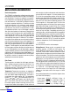
STOP
2990 F04
START ADDRESS R/W
P
981-71-71-7
a6-a0 b7-b0 b7-b0
9898
S
DATA DATAACK ACK ACK
Figure4. Data Transfer Over I
2
C or SMBus
S A A DATAW#ADDRESS COMMAND A
0 0 b7:b0010011a1:a0
FROM MASTER TO SLAVE
XXXXXb3:b0 0
2990 F05
P
FROM SLAVE TO MASTER
A: ACKNOWLEDGE (LOW)
A#: NOT ACKNOWLEDGE (HIGH)
R: READ BIT (HIGH)
W#: WRITE BIT (LOW)
S: START CONDITION
P: STOP CONDITION
Figure5. LTC2990 Serial Bus Write Byte Protocol
Downloaded from Arrow.com.Downloaded from Arrow.com.Downloaded from Arrow.com.Downloaded from Arrow.com.Downloaded from Arrow.com.Downloaded from Arrow.com.Downloaded from Arrow.com.Downloaded from Arrow.com.Downloaded from Arrow.com.Downloaded from Arrow.com.Downloaded from Arrow.com.Downloaded from Arrow.com.Downloaded from Arrow.com.Downloaded from Arrow.com.