
Datasheet


LTC2240-12
3
224012fd
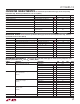
CONVERTER CHARACTERISTICS
PARAMETER CONDITIONS MIN TYP MAX UNITS
Resolution (No Missing Codes)
l
12 Bits
Integral Linearity Error Differential Analog Input (Note 5)
l
–2.1 ±0.6 2.1 LSB
Differential Linearity Error Differential Analog Input
l
–1 ±0.4 1 LSB
Offset Error (Note 6)
l
–15 ±5 15 mV
Gain Error External Reference
l
–3.5 ±0.7 3.5 %FS
Offset Drift ±10 μV/C
Full-Scale Drift Internal Reference
External Reference
±60
±45
ppm/C
ppm/C
Transition Noise SENSE = 1V 0.74 LSB
RMS
The l denotes the specifi cations which apply over the full operating
temperature range, otherwise specifi cations are at T
A
= 25°C. (Note 4)
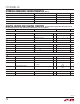
ANALOG INPUT
The l denotes the specifi cations which apply over the full operating temperature range, otherwise
specifi cations are at T
A
= 25°C. (Note 4)
SYMBOL PARAMETER CONDITIONS MIN TYP MAX UNITS
V
IN
Analog Input Range (A
IN
+
– A
IN
–
) 2.375V < V
DD
< 2.625V (Note 7)
l
±0.5 to ±1 V
V
IN, CM
Analog Input Common Mode (A
IN
+
+ A
IN
–
)/2 Differential Input (Note 7)
l
1.2 1.25 1.3 V
I
IN
Analog Input Leakage Current 0 < A
IN
+
, A
IN
–
< V
DD
l
–1 1 μA
I
SENSE
SENSE Input Leakage 0V < SENSE < 1V
l
–1 1 μA
I
MODE
MODE Pin Pull-Down Current to GND 7 μA
I
LVDS
LVDS Pin Pull-Down Current to GND 7 μA
t
AP
Sample and Hold Acquisition Delay Time 0.4 ns
t
JITTER
Sample and Hold Acquisition Delay Time Jitter 95 fs
RMS
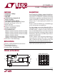
Full Power Bandwidth Figure 8 Test Circuit 1200 MHz
DYNAMIC ACCURACY
The l denotes the specifi cations which apply over the full operating temperature range,
otherwise specifi cations are at T
A
= 25°C. A
IN
= –1dBFS. (Note 4)
SYMBOL PARAMETER CONDITIONS MIN TYP MAX UNITS
SNR Signal-to-Noise Ratio (Note 10) 10MHz Input 65.6 dB
70MHz Input
l
64.2 65.5 dB
140MHz Input 65.4 dB
240MHz Input 65.2 dB
SFDR Spurious Free Dynamic Range
2nd or 3rd Harmonic
(Note 11)
10MHz Input 80 dB
70MHz Input
l
65 75 dB
140MHz Input 74 dB
240MHz Input 72 dB
Spurious Free Dynamic Range
4th Harmonic or Higher
(Note 11)
10MHz Input 87 dB
70MHz Input
l
76 87 dB
140MHz Input 87 dB
240MHz Input 87 dB
S/(N+D) Signal-to-Noise Plus
Distortion Ratio
(Note 12)
10MHz Input 65.5 dB
70MHz Input
l
62.7 65.3 dB
140MHz Input 65.2 dB
240MHz Input 64.2 dB
IMD Intermodulation Distortion f
IN1
= 135MHz, f
IN2
= 140MHz 81 dBc