
Datasheet


LTC1960
5
1960fb
Note 1: Stresses beyond those listed under Absolute Maximum Ratings
may cause permanent damage to the device. Exposure to any Absolute
Maximum Rating condition for extended periods may affect device
reliability and lifetime.
Note 2. Battery voltage must be adequate to drive gates of PowerPath
P-channel FET switches. This does not affect charging voltage of the
battery, which can be zero volts.
Note 3. See Test Circuit.
Note 4. DCIN, BAT1, BAT2 are held at 12V and GDCI, GB1I, GB2I are
forced to 10.5V. SCP is set at 12.0V to measure source current at GDCI,
SYMBOL PARAMETER CONDITIONS MIN TYP MAX UNITS
t
ONPI
Gate B1I/B2I/DCI Turn-On Time V
GS
< –3V, C
LOAD
= 3nF (Note 5) 300 µs
t
OFFPI
Gate B1I/B2I/DCI Turn-Off Time V
GS
> –1V, C
LOAD
= 3nF (Note 5) 10 µs
V
PONI
Input Gate Clamp Voltage
GB1I
GB2I
GDCI
I
LOAD
= 1µA
Highest (V
BAT1
or V
SCP
) – V
GB1I
Highest (V
BAT2
or V
SCP
) – V
GB2I
Highest (V
DCIN
or V
SCP
) – V
GDCI
4.75
4.75
4.75
6.7
6.7
6.7
7.5
7.5
7.5
V
V
V
V
POFFI
Input Gate Off Voltage
GB1I
GB2I
GDCI
I
LOAD
= 25µA
Highest (V
BAT1
or V
SCP
) – V
GB1I
Highest (V
BAT2
or V
SCP
) – V
GB2I
Highest (V
DCIN
or V
SCP
) – V
GDCI
0.18
0.18
0.18
0.25
0.25
0.25
V
V
V
Logic I/O
I
IH
/I
IL
SSB/SCK/MOSI Input High/Low Current
l
–1 1 µA
V
IL
SSB/MOSI/SCK Input Low Voltage
l
0.8 V
V
IH
SSB/MOSI/SCK Input High Voltage
l
2 V
V
OL
MISO Output Low Voltage I
OL
= 1.3mA
l
0.4 V
I
OFF
MISO Output Off-State Leakage Current V
MISO
= 5V
l
2 µA
SPI Timing (See Timing Diagram)
T
WD
Watch Dog Timer
l
1.2 2.5 4.5 sec
t
SSH
SSB High Time 680 ns
t
CYC
SCK Period C
LOAD
= 200pF R
PULLUP
= 4.7k on MISO
l
2 µs
t
SH
SCK High Time 680 ns
t
SL
SCK Low Time 680 ns
t
LD
Enable Lead Time 200 ns
t
LG
Enable Lag Time 200 ns
t
su
Input Data Set-Up Time
l
100 ns
t
H
Input Data Hold Time
l
100 ns
t
A
Access Time (From Hi-Z to Data Active on MISO)
l
125 ns
t
dis
Disable Time (Hold Time to Hi-Z State on MISO)
l
125 ns
t
V
Output Data Valid C
L
= 200pF, R
PULLUP
= 4.7k on MISO
l
580 ns
t
HO
Output Data Hold
l
0 ns
t
Ir
SCK/MOSI/SSB Rise Time 0.8V to 2V 250 ns
t
If
SCK/MOSI/SSB Fall Time 2V to 0.8V 250 ns
t
Of
MISO Fall Time 2V to 0.4V, C
L
= 200pF
l
400 ns
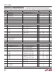
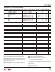
ELECTRICAL CHARACTERISTICS
The l denotes the specifications which apply over the full operating
temperature range (Note 7), otherwise specifications are at T
A
= 25°C. V
DCIN
= 20V, V
BAT1
= 12V, V
BAT2
= 12V, unless otherwise noted.
GB1I and GB2I. SCP is set at 11.9V to measure sink current at GDCI, GB1I
and GB2I.
Note 5. Extrapolated from testing with C
L
= 50pF.
Note 6. VDAC offset is equal to the reference voltage, since
V
OUT
= V
REF
(16mV • VDAC
(VALUE)
/2047 + 1)
Note 7. The LTC1960C is guaranteed to meet specified performance from
0°C to 70°C and is designed, characterized and expected to meet specified
performance at –40°C and 85°C, but is not tested at these extended
temperature limits.
Note 8. Does not apply to low current mode. Refer to “The Current DAC
Block” in the Operation section.