
Datasheet


LTC1960
3
1960fb
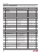
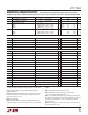
ELECTRICAL CHARACTERISTICS
SYMBOL PARAMETER CONDITIONS MIN TYP MAX UNITS
Supply and Reference
DCIN Operating Range DCIN Selected 6 28 V
I
CH
DCIN Operating Current Not Charging (DCIN Selected)
Charging (DCIN Selected)
1
1.3
1.5
2
mA
mA
Battery Operating Voltage Range Battery Selected, PowerPath Function (Note 2) 6 28 V
Battery Drain Current Battery Selected, Not Charging, V
DCIN
= 0V 175 µA
V
FDC
V
FB1
V
FB2
V
FSCN
V
PLUS
Diodes Forward Voltage:
DCIN to V
PLUS
BAT1 to V
PLUS
BAT2 to V
PLUS
SCN to V
PLUS
I
VCC
= 10mA
I
VCC
= 0mA
I
VCC
= 0mA
I
VCC
= 0mA
0.8
0.7
0.7
0.7
V
V
V
V
UVLO Undervoltage Lockout Threshold V
PLUS
Ramping Down, Measured at V
PLUS
to GND
l
3 3.5 3.9 V
UVHYS UV Lockout Hysteresis V
PLUS
Rising, Measured at V
PLUS
to GND 60 mV
V
VCC
V
CC
Regulator Output Voltage 5 5.2 5.4 V
V
LDR
V
CC
Load Regulation I
VCC
= 0mA to 10mA 0.2 1 %
Switching Regulator
V
TOL
Overall Voltage Accuracy 5V ≤ V
OUT
< 25V, (Note 3)
l
–0.8
–1
0.8
1
%
%
I
TOL
Overall Current Accuracy IDAC Value = 3FF
HEX
V
CSP
, V
CSN
= 12V
l
–5
–6
5
6
%
%
f
OSC
Regulator Switching Frequency 255 300 345 kHz
f
DO
Regulator Switching Frequency in Low
Dropout Mode
Duty Cycle ≥ 99% 20 25 kHz
DC
MAX
Regulator Maximum Duty Cycle 99 99.5 %
I
MAX
Maximum Current Sense Threshold V
ITH
= 2.2V 140 155 190 mV
I
SNS
CA1 Input Bias Current V
CSP
= V
CSN
> 5V 150 µA
CMSL CAI Input Common Mode Low 0 V
CMSH CAI Input Common Mode High V
DCIN
–0.2 V
V
CL1
CL1 Turn-On Threshold 95 100 105 mV
TG t
r
TG t
f
TGATE Transition Time:
TGATE Rise Time
TGATE Fall Time
C
LOAD
= 3300pF, 10% to 90%
C
LOAD
= 3300pF, 10% to 90%
50
50
90
90
ns
ns
BG t
r
BG t
f
BGATE Transition Time:
BGATE Rise Time
BGATE Fall Time
C
LOAD
= 3300pF, 10% to 90%
C
LOAD
= 3300pF, 10% to 90%
50
40
90
80
ns
ns
Trip Points
V
TR
DCDIV/LOPWR Threshold V
DCDIV
or V
LOPWR
Falling
l
1.166 1.19 1.215 V
V
THYS
DCDIV/LOPWR Hysteresis Voltage V
DCDIV
or V
LOPWR
Rising 30 mV
I
BVT
DCDIV/LOPWR Input Bias Current V
DCDIV
or V
LOPWR
= 1.19V 20 200 nA
V
TSC
Short-Circuit Comparator Threshold V
SCP
– V
SCN
, V
CC
≥ 5V
l
90 100 115 mV
V
FTO
Fast PowerPath Turn-Off Threshold V
DCDIV
Rising from V
CC
6 7 7.9 V
V
OVSD
Overvoltage Shutdown Threshold as a Percent
of Programmed Charger Voltage
V
SET
Rising from 0.8V Until TGATE and
BGATE Stop Switching
107 %
The l denotes the specifications which apply over the full operating
temperature range (Note 7), otherwise specifications are at T
A
= 25°C. V
DCIN
= 20V, V
BAT1
= 12V, V
BAT2
= 12V, unless otherwise noted.