
Datasheet


LTC1960
18
1960fb
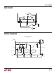
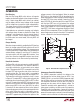
The Current DAC Block
The current DAC is a delta-sigma modulator which controls
the effective value of an internal resistor, R
SET
= 18.77k,
used to program the maximum charger current. Figure 6 is
a simplified diagram of the DAC operation. The delta-sigma
modulator and switch convert the IDAC value, received
via SPI communication, to a variable resistance equal to
1.25R
SET
/(IDAC
(VALUE)
/1023). In regulation, I
SET
is servo
driven to the 0.8V reference voltage, V
REF
, and the cur-
rent from R
SET
is matched against a current derived from
the voltage between pins CSP and CSN. This current is
(V
CSP
– V
CSN
)/3k.
Therefore, programmed current is:
I
AVG
=
V
REF
• 3k
(1.25R
SNS
R
SET
)
•
IDAC
(VALUE)
1023
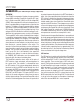
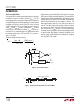
When the low current mode bit (D10) is set to 1, the current
DAC enters a different mode of operation. The current DAC
output is pulse-width modulated with a high frequency clock
having a duty cycle value of 1/8. Therefore, the maximum
output current provided by the charger is I
MAX
/8. The
delta-sigma output gates this low duty cycle signal on
and off. The delta-sigma shift registers are then clocked
at a slower rate, about 40ms/bit, so that the charger has
time to settle to the I
MAX
/8 value. The resulting average
charging current is equal to 1/8 of the current programmed
in normal mode. Dual battery charging is disabled in low
current mode. If both batteries are selected for charging,
then only BAT1 will charge.
OPERATION
Figure 6. Current DAC Operation
Figure 7. Charging Current Waveform in Low Current Mode
–
+
1960 F06
V
REF
I
SET
R
SET
18.77k
∆Σ
MODULATOR
10
TO
I
TH
DAC
VALUE
(10 BITS)
C
SET
(V
CSP
– V
CSN
)
3kΩ
(FROM CA1 AMPLIFIER)
AVERAGE CHARGER CURRENT
I
MAX
/8
0
~40ms
1960 F07