
Datasheet


3
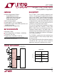
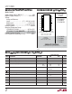
LTC1090
1090fc
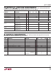
CO VERTER A D ULTIPLEXER CHARACTERISTICS
U
W
U
LTC1090A LTC1090
PARAMETER CONDITIONS MIN TYP MAX MIN TYP MAX UNITS
Offset Error (Note 4) ● ±0.5 ±0.5 LSB
Linearity Error (Notes 4 and 5) ● ±0.5 ±0.5 LSB
Gain Error (Note 4) ● ±1.0 ±2.0 LSB
Total Unadjusted Error V
REF
= 5.000V ● ±1.0 LSB
(Notes 4 and 6)
Reference Input Resistance 10 10 kΩ
Analog and REF Input Range (Note 7) (V
–
) – 0.05V to V
CC
0.05V V
On Channel Leakage Current On Channel = 5V ● 11µA
(Note 8) Off Channel = 0V
On Channel = 0V ● –1 –1 µA
Off Channel = 5V
Off Channel Leakage Current On Channel = 5V ● –1 –1 µA
(Note 8) Off Channel = 0V
On Channel = 0V ● 11µA
Off Channel = 5V
The ● denotes specifications which
apply over the full operating temperature range, otherwise specifications are T
A
= 25°C. (Note 3)
LTC1090/LTC1090A
SYMBOL PARAMETER CONDITIONS MIN TYP MAX UNITS
t
ACC
Delay Time From CS
↓
to D
OUT
Data Valid (Note 9) 2 ACLK Cycles
t
SMPL
Analog Input Sample Time See Operating Sequence 5 SCLK Cycles
t
CONV
Conversion Time See Operating Sequence 44 ACLK Cycles
t
dDO
Delay Time, SCLK
↓
to D
OUT
Data Valid See Test Circuits ● 250 450 ns
t
dis
Delay Time, CS
↑
to D
OUT
Hi-Z See Test Circuits ● 140 300 ns ns
t
en
Delay Time, 2nd CLK
↓
to D
OUT
Enabled See Test Circuits ● 150 400 ns ns
t
hDO
Time Output Data Remains Valid After SCLK
↓
50 ns
t
f
D
OUT
Fall Time See Test Circuits ● 90 300 ns ns
t
r
D
OUT
Rise Time See Test Circuits ● 60 300 ns ns
C
IN
Input Capacitance Analog Inputs On Channel 65 pF
Off Channel 5 pF
Digital Inputs 5 pF
The ● denotes specifications which apply over the full operating
temperature range, otherwise specification are T
A
= 25°C. (Note 3)
AC ELECTRICAL CHARACTERISTICS