
Instruction Manual

2
dc2369af
DEMO MANUAL DC2369A
DC2369A CONNECTIONS AND JUMPERS
1. Set the slide switch SW1 to ON to power on the circuit.
DC2369A is powered from its included two AAA batteries
and therefore does not need an external power supply.
The slide switch asserts the enable pin of the LTC3335.
You may verify correct operation of the power supplies
by measuring (on the back of the circuit board) that
V
DD
– GND = 3.3V and V
REF
– GND = 3.0V.
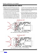
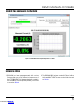
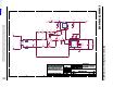
2. The only external connection needed to the DC2369A is
for the current to be measured. The DC2369A circuitry
does not draw its power from this current – it only uses it
to develop a small voltage drop across the included 10mΩ
sense resistor. The DC2369A is designed to measure up
to ±1A full-scale current, developing a ±10mV voltage
drop across the sense resistor. Connect the current to
be measured using the banana connectors (J2 and J3).
Set jumpers JP1 and JP2 to the INT position (to use the
internal sense resistor). See Figure 1.
3. Alternatively, DC2369A can be used to measure the volt
-
age across an external sense resistor. In this case, set
jumpers JP1 and JP2 to EXT, and connect the voltage
to be measured to the turrets labeled V
IN
+
and V
IN
–
.
The preconfigured DC2369A firmware and software
will still assume a ±10mV full-scale input voltage and
report that as a ±1A full-scale current. See Figure 2.
Figure 2. DC2369A Connections and Jumpers for External Sense Resistor
Figure 1. DC2369A Connections and Jumpers for Internal Sense Resistor
Downloaded from Arrow.com.Downloaded from Arrow.com.