
User Manual


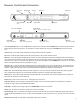


Table Of Contents

Receiver Controls and Connectors
Channel Up & Down buttons. Press the UP button to select the next channel. Press the DOWN button to select the previous channel.
Button sequence does not wrap around. For example, once CH5 is selected you must press the DOWN button four times to reach
CH1.
Channel LEDs. A blue LED will light indicating the currently selected channel of operation.
RF LED. A red LED will light indicating that an RF signal is present on the currently selected channel.
Mode LED. A red LED will light indicating that they receiver is currently operating in a backwards compatible mode to allow operation
with original XDT1 transmitters. Please note that while in this mode, the frequency response of the system is that of the original XDR1
receiver (10 Hz - 12 kHz). To enter this mode, power the unit off, press and hold the Channel DOWN button and power up. The unit will
remain in this mode until the power is cycled off then on again.
Receiver LEDs. A green LED will light indicating that the unit is receiving data on one of four internal receivers. The unit houses four
separate internal receivers, two of which include internal antenna meaning that the system will operate even without external antenna
attached. *Please note that range may be adversely affected without attaching the supplied 1/2 wave antenna.
Audio LEDs. Blue LEDs will light indicating the audio signal level. There is no need for a CLIP indicator as the system has greater
than 118 dB dynamic range and can accommodate input/output signals up to 6V peak-to-peak (approximately).
Battery LEDs. Green LEDs will light indicating remaining battery life in the transmitter. Each tall bar represents one-hour segments.
Each short bar represents 20 minute segments.
Power button. Press once to turn the unit on. Press again to turn the unit off.
Antenna A & B input connector (BNC). Diversity antenna inputs A and B. Connect the supplied 1/2 wave antenna for maximum
performance range. Antenna inputs ARE NOT DC biased.
Cable Grip. Thread the power supply cable into the CABLE GRIP to secure the connection.
Power input. DC socket for connection of mains unit, 9V 500 ma (supplied).
Instrument Out. This 1/4” unbalanced TRS output jack (1.8 kΩ) is voiced at the tip for instrument applications (gentle high-frequency
role off at 8 kHz approximates sound of a 15’ cable), and full bandwidth (10 Hz to 20 kHz) on the ring. Great for ‘tuner’ out or dual amp
setups.
Balanced Low Z. Balanced XLR, 600Ω, full-bandwidth output (10 Hz to 20 kHz).
Channel Up
button
Channel Down
button
Power supply Cable Grip
Instrument Out
output 1/4” TRS jack - unbalanced, 1.8kΩ
Balanced Low Z
output XLR(F) - 600Ω
Antenna B
input connector (BNC)
Power Mains
input connector (ASA120 type)
Channel LEDs Audio LEDs
RF LED
Mode LED
Receiver LEDs
Battery LEDs
Power button
Antenna A
input connector (BNC)
2
Balanced Low Z
Instrument Out
9V DC 500ma
(center negative)
antenna B in
antenna A in