Regulatory notes and statements Wireless LAN, Health and Authorization for use 108Mbps Super-G TM Wireless LAN Router Radio frequency electromagnetic energy is emitted from Wireless LAN devices. The energy levels of these emissions however are far much less than the electromagnetic energy emissions from wireless devices like for example mobile phones. Wireless LAN devices are safe for use frequency safety standards and recommendations.
FCC Radio Frequency Exposure statement This Wireless LAN radio device has been evaluated under FCC Bulletin OET 65 and found compliant to the requirements as set forth in CFR 47 Sections 2.1091, 2.1093, and 15.247 (b) (4) addressing RF Exposure from radio frequency devices. The radiated output power of this Wireless LAN device is far below the FCC radio frequency exposure limits.
TABLE OF CONTENT Unpacking ............................................................................................................................................................................................. 4 Setup ..................................................................................................................................................................................................... 4 Dynamic..............................................................................
ABOUT THIS GUIDE INTRODUCTION Congratulations on your purchase of this 108Mbps Super-GTM Wireless LAN Router. This integrated access device combines Internet gateway functions with wireless LAN and Fast Ethernet switch. It provides a complete solution for Internet surfing and office resources sharing, and it is easy to configure and operate for every users.
Features: High speed data transfer rate Supports NAT for share 1 IP address to all LAN/WLAN users. Supports PPPoE and PPTP protocol for Dial-Up ADSL. Supports 64/128 bit WEP Encryption Supports WPA-PSK, WPA2-PSK, WPA, WPA2 security Supports DHCP Server / Client. Supports UPnP (Universal Plug and Play). Supports Virtual Server mapping. Supports Packet filtering. Supports Protocol filtering Support Domain filtering Supports DNS Simple Firewall protection. Upgradeable firmware for future function.
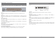
HARDWARE INSTALLATION Front Panel The figure below shows the front panel of the 108Mbps Super-GTM Wireless LAN Router. Rear Panel The figure below shows the rear panel of the 108Mbps Super-GTM Wireless LAN Router. Rear Panel Front Panel Power This indicator lights green when the hub is receives power, otherwise it is off. Status This indicator blinking green means the WLAN Router is working successful. Otherwise, this indicator always on or off means the function of the WLAN Router is fail.
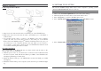
Hardware connections PC NETWORK TCP/IP SETTING Connecting the WLAN Router The network TCP/IP settings differ based on the computer’s operating system (Win95/98/ME/NT/2000/XP) and are as follows. Windows 95/98/ME 1. Click on the “Network neighborhood” icon found on the desktop. 2. Click the right mouse button and a context menu will be show. 3. Select “Properties” to enter the TCP/IP setting screen. 4. Select “Obtain an IP address automatically” on the “IP address” field. 1.
6. Select “None” for the “Gateway address” field. Windows XP Point the cursor and click the right button on the “My Network Place” icon. Select “properties” to enter the TCP/IP setting window. 1. Set “IP address” to “Obtain an IP address automatically.” 2. Set “DNS” to “Obtain DNS server address automatically.” Windows 2000 Double click on the “My computer” icon on the desktop. When “My computer” window opens, open the “Control panel” and then open the “Network dialup connection” applet.
CONFIGURATION First make sure that the network connections are functioning normally. This WLAN Router can be configured using Internet Explorer 5.0 or newer web browser versions. Login to the WLAN Router through Wireless LAN Before configuring the WLAN Router through WLAN, make sure that the SSID, Channel and the WEP is set properly.
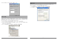
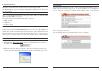
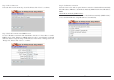
Step 2: Choose time zone Select the time zone from the drop down list. Please click “Next” to continue. Step 4: Set Internet connection Select how the router will set up the Internet connection: Obtained IP automatically; Fixed IP address; PPPoE to obtain IP automatically; PPPoE with a fixed IP address; PPTP. Obtain IP automatically (DHCP client): If user has enabled DHCP server, choose "Obtain IP automatically (DHCP client)" to have the WLAN Router assign IP addresses automatically.
Fixed IP Address: PPPoE to obtain IP automatically: If the Internet Service Providers assign a fixed IP address, choose this option and enter the assigned IP address, subnet mask, gateway IP and DNS IP addresses for the WLAN Router. If connected to the Internet using a PPPoE (Dial-up xDSL) Modem, the ISP will provide a Password and User Name, and then the ISP uses PPPoE. Choose this option and enter the required information.
PPPoE with a fixed IP address: PPTP: If connected to the Internet using a PPPoE (Dial-up xDSL) Modem, the ISP will provide a Password, User Name and a Fixed IP Address, choose this option and enter the required information. If connected to the Internet using a (PPTP) xDSL Modem, enter the your IP Address, Subnet Mask, Gateway, Server IP, PPTP Account and PPTP Password, Your Subnet Mask required by your ISP in the appropriate fields.
Step 5: Set Wireless LAN connection Click “Enable” to enable wireless LAN. If user enables the wireless LAN, type the SSID in the text box and select a communications channel. The SSID and channel must be the same as wireless devices attempting communication to the router. L2TP: If connected to the Internet using a L2TP (Dial-up xDSL) Modem, the ISP will provide a Server IP. Account and Password. Choose this option and enter the required information.
Advanced configuration LAN Setting The screen enables user to configure the LAN & DHCP Server, set WAN parameters, create Administrator and User passwords, and set the local time, time zone, and dynamic DNS. LAN & DHCP Server This page leads to set LAN and DHCP properties, such as the host name, IP address, subnet mask, and domain name. LAN and DHCP profiles are listed in the DHCP table at the bottom of the screen. Host Name: Type the host name in the text box. The host name is required by some ISPs.
Password This screen enables user to set administrative and user passwords. These passwords are used to gain access to the router interface. Administrator: Type the password the Administrator will use to log in to the system. The password must be typed again for confirmation. The authority if Administrator allow user configuration of the WLAN Router. User: Type the password the User will use to log in to the system. The password must be typed again for confirmation.
Wireless This section enables user to configuration the wireless communications parameters for the WLAN Router. Authentication The authentication type default is set to disable. There are four options: Disable, WEP, WPA, and WPA2. Basic This page allow user to enable and disable the wireless LAN function, create a SSID, and select the channel for wireless communications. Authentication Type: The authentication type default is set to open system.
Key 1 ~ Key 4: Enables user to create an encryption scheme for Wireless LAN transmissions. Manually enter a set of values for each key. Select a key to use by clicking the radio button next to the key. Click “Clear” to erase key values. WPA/WPA2 Security If WPA or WPA2 is selected, the below screen is shown. Please set the length of the encryption key and the parameters for the RADIUS server. Lifetime: Select the Lifetime of the Encryption Key from 5 Minutes to 1 Day.
Status This selection enables user to view the status of the router LAN, WAN and Wireless connections, and view logs and statistics pertaining to connections and packet transfers. Device Information This screen enables user to view the router LAN, Wireless and WAN configuration. Firmware Version: Displays the latest build of the router firmware interface. After updating the firmware in Tools - Firmware, check this to ensure that the firmware was successfully updated.
Log Setting This screen enables user to set router logging parameters. Statistic This screen displays a table that shows the rate of packet transmission via the router LAN, Wireless and WAN ports (in bytes per second). SMTP Server: Type the SMTP server address for the email that the log will be sent to in the next field. Send to: Type an email address for the log to be sent to. Click “Email Log Now” to immediately send the current log.
Routing This selection enables user to set how the router forwards data: Static and Dynamic. Routing Table enables user to view the information created by the router that displays the network interconnection topology. Dynamic This screen enables user to set NAT parameters. Static It enables user to set parameters by which the router forwards data to its destination if user’s network has a static IP address. Network Address: Type the static IP address user’s network uses to access the Internet.
Access This page enables you to define access restrictions, set up protocol and IP filters, create virtual servers, define access for special applications such as games, and set firewall rules. MAC Filters Filters Using filters to deny or allow the users to access. Five types of filters to select: MAC, URL blocking, IP, Protocol filter and Domain blocking. MAC Filter: Enables you to allow or deny Internet access to users within the LAN based upon the MAC address of their network interface.
URL Blocking IP Filters You could enable URL blocking to deny the users from accessing the specified URL. Add those specified URL in the text box. This screen enables you to define a minimum and maximum IP address range filter; all IP addresses falling in the range are not allowed Internet access. The IP filter profiles are listed in the table at the bottom of the page. (Note: Click anywhere in the item. Once the line is selected, the fields automatically load the item' s parameters, which you can edit.
Domain Blocking Protocol Filters You could specify the domains that allow users to access or deny by clicking one of the two items. Also, add the specified domains in the text box. This screen enables you to allow and deny access based upon a communications protocol list you create. The protocol filter profiles are listed in the table at the bottom of the page. Note: When selecting items in the table at the bottom, click anywhere in the item.
Virtual Server This screen enables user to create a virtual server via the router. If the router is set as a virtual server, remote users requesting Web or FTP services through the WAN are directed to local servers in the LAN. The router redirects the request via the protocol and port numbers to the correct LAN server. The Virtual Sever profiles are listed in the table at the bottom of the page. Note: When selecting items in the table at the bottom, click anywhere in the item.
Trigger: Defines the outgoing communication that determines whether the user has legitimate access to the application. Protocol: Select the protocol (TCP, UDP, or ICMP) that can be used to access the application. Port Range: Type the port range that can be used to access the application in the text boxes. Incoming: Defines which incoming communications users are permitted to connect with. Protocol: Select the protocol (TCP, UDP, or ICMP) that can be used by the incoming communication.
Delete: Select a list item and click “Delete” to remove the item from the list. New: Click “New” to erase all fields and enter new information. Priority Up: Select a rule from the list and click “Priority Up” to increase the priority of the rule. Priority Down: Select a rule from the list and click “Priority Down” to decrease the priority of the rule. Update Priority: After increasing or decreasing the priority of a rule, click “Update Priority” to save the changes.
Tools This page enables user to restart the system, save and load different settings as profiles, restore factory default settings, run a setup wizard to configure router settings, upgrade the firmware, and ping remote IP addresses. Reset Click “Restart” to restart the system in the event the system is not performing correctly. Settings This screen enables user to save settings as a profile and load profiles for different circumstances.
TECHNICAL SPECIFICATIONS General Standards Protocol Radio Technology Data Transfer Rate Topology Receiver Sensitivity TX Power Network Cables Frequency Range Modulation Schemes Security Channels Number of Ports IEEE 802.3u 100BASE-TX Fast Ethernet IEEE 802.11g; IEEE 802.11b CSMA/CD IEEE 802.11g Orthogonal Frequency Division Modulation 802.11b: 1, 2, 5.5, 11Mbps (auto sense) 802.