Dual Rail Modular KVM Console with 15 / 17 / 19”LCD Panel English User Manual For Installation into a 19” rack it is essential to precisely follow the installation procedure as described in section 3.1. Install the Console into a Cabinet of this manual.
Dual Rail Console For Modular KVM Switch User Guide Packing List The complete 15 / 17 / 19” dual rail console for modular KVM switch package consists of: • • • • • • • • • • 1U 19” rack mount console Rail with front and rear bracket x 2 Blockers x 2 1.8 m KVM cable.
Dual Rail Console For Modular KVM Switch User Guide Safety Instructions Please read these safety instructions carefully. Please keep this User’s Manual for later reference. Please disconnect this equipment from the AC outlet before cleaning. Do not use liquid or sprayed detergent for cleaning. Use a moist sheet or cloth for cleaning. It is recommended that for your convenience the equipment is installed near an easily accessible power socket. Please keep this equipment in a non-humid environment.
Dual Rail Console For Modular KVM Switch User Guide Index of Contents Packing List ............................................................................................................... 1 Safety Instructions ..................................................................................................... 2 Index of Contents ...................................................................................................... 3 1. General Information.............................................
Dual Rail Console For Modular KVM Switch User Guide 1. General Information The LINDY Dual Rail consoles offer an industrial level input solution to optimize your space utilization by controlling your systems in just 1U. With the unique modular design, you can easily integrate with more than 17 models of KVM switch, with different functions, and expand up to 8 levels of KVM switch. 1.1.
Dual Rail Console For Modular KVM Switch User Guide 1.3. Product Specification 1.3.1. 15" Dual Rail Console with Modular KVM Switch Specification Model name Number of ports Dimension Package Dimension Net Weight Gross Weight Display Size Panel Type Resolution Capabilities Pixel Pitch Viewing Angle (CR>10) Contrast Ratio Brightness Back Light Supported Colors Response Time 15” dual rail console with modular KVM switch 1 459.6 x 448.3 x 44 mm / 18.1 x 17.6 x 1.7 inches 606 x 551.5 x 230 mm / 23.9 x 21.
Dual Rail Console For Modular KVM Switch User Guide 1.3.2. 17" Dual Rail Console with Modular KVM Switch Specification Model name Number of ports Dimension Package Dimension Net Weight Gross Weight Display Size Panel Type Resolution Capabilities Pixel Pitch Viewing Angle (CR>10) Contrast Ratio Brightness Back Light Supported Colors Response Time 17” dual rail console with modular KVM switch 1 459.6 x 448.3 x 44 mm / 18.1 x 17.6 x 1.7 inches 606 x 551.5 x 230 mm / 23.9 x 21.7 x 9.0 inches 13 Kg / 28.
Dual Rail Console For Modular KVM Switch User Guide 1.3.3. 19" Dual Rail Console with Modular KVM Switch Specification Model name Number of ports Dimension Package Dimension Net Weight Gross Weight Display Size Panel Type Resolution Capabilities Pixel Pitch Viewing Angle (CR>10) Contrast Ratio Brightness Back Light Supported Colors Response Time 19” dual rail console with modular KVM switch 1 539.6 x 448.3 x 44 mm / 21.2 x 17.6 x 1.7 inches 606 x 551.5 x 230 mm / 23.9 x 21.7 x 9.0 inches 13 Kg / 28.
Dual Rail Console For Modular KVM Switch User Guide 2. Panel Controls & OSD Function Panel Controls Description Soft power on/off button. Adjacent LED is lit when on Auto Auto-synchronize and scale down display to any valid factory preset timings Up Press to scroll the function you want to adjust Down Press to scroll the function you want to adjust Menu To access the main menu. This button also acts as the “Enter” button 2.1. Auto Tune 1. Press Menu 2.
Dual Rail Console For Modular KVM Switch User Guide 2.3. Brightness 1. Press Menu 2. 3. 4. 5. Use the Up and Down buttons to scroll to Brightness Press Menu to enter Use the Up and Down buttons to adjust the Brightness of the display Press Menu to enter 2.4. Contrast 1. Press Menu 2. Use the Up and Down buttons to scroll to Contrast 3. Press Menu to enter 4. Use the Up and Down buttons to adjust the Contrast of the display 5. Press Menu to enter 2.5. Colour 1. Press Menu 2.
Dual Rail Console For Modular KVM Switch User Guide 2.6. Position 1. Press Menu 2. Use the Up and Down buttons to scroll to Positioning 3. Press Menu to enter. You will see: Icon Description Image Pos To adjust the position of the image. OSD Pos To adjust the position of the OSD. Return To exit and return to the previous page 4. Use the Up and Down buttons to choose which Position you want to change 5. Press Menu to enter 2.7. Language 1. Press Menu 2.
Dual Rail Console For Modular KVM Switch User Guide 3. Installation 3.1. Install the Console into a Cabinet 3.1.1. Notes It is essential that each step of this installation guide is completed in the stated order to ensure a successful installation. It is highly recommended that two persons carry out the installation. 1. Please the contents of this box against the list below, before installation. 2. Before installation, make sure all peripherals and computer have been turned off. 3.
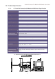
Dual Rail Console For Modular KVM Switch User Guide 3.1.3. Installing the Console 1. Adjust the rail with the rear bracket to fit your cabinet 2. Attach the front and rear brackets to your cabinet 3. Repeat steps 1 and 2 for the other side of your cabinet 4. Slide the console along the rails until you reach the end 5.
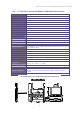
Dual Rail Console For Modular KVM Switch User Guide 6. Install three screws (length 6mm) to the rear of the console at each side to complete the installation 3.2. Install Modular KVM Switch (OPTIONAL MODULE) 3.2.1. Hardware Kits Contents 1. Bracket A with thumb screw x 2 2. Screw (length 6 mm) x 4 3.2.2. Install Modular KVM Switch Step 1.
Dual Rail Console For Modular KVM Switch User Guide 2. From the rear of the cabinet slide the KVM Switch along the rails, until it reaches the console and the thumb screws are aligned to the rear of the cabinet Plastic Rail on KVM Switch Rear View of Rail 3.
Dual Rail Console For Modular KVM Switch User Guide 3.3. Installing the Video Card and Video Driver Before connecting the LCD console, make sure your computer has a video card already installed for the monitor. After you connect the console, install the video driver. The video driver is supplied by the video card manufacturer and may be found on the CD-ROM that came with your computer. If you need information on installing a video card or video driver, refer to the manual that came with your video card. 3.
Dual Rail Console with Modular KVM Switch User’s Manual 3.3.2. Connecting the Console To connect an LCD console to a computer, perform the following steps PS/2-USB switch 1. Turn off your computer. You should always turn off your computer before connecting or disconnecting a device. 2. Connect the video (VGA) connector of the KVM cable to the video card connector on the rear panel of your computer. 3.
Dual Rail Console with Modular KVM Switch User’s Manual better suit your video card and your personal preference. Refer to Chapter 2 for more information on using the on-screen menu to adjust the video display. Before you begin, make sure that powers to all the devices you will be connecting up have been turned off. To prevent damage to your installation due to ground potential difference, make sure that all the devices on the installation are properly grounded. 4.
WEEE, Recycling of Electronic Products (Europe) WEEE (Waste of Electrical and Electronic Equipment), Recycling of Electronic Products In 2006 the European Union introduced regulations (WEEE) for the collection and recycling of all waste electrical and electronic equipment. It is no longer allowable to simply throw away electrical and electronic equipment. Instead, these products must enter the recycling process.
Radio Frequency Energy, Certifications Shielded cables must be used with this equipment to maintain compliance with radio frequency energy emission regulations and ensure a suitably high level of immunity to electromagnetic disturbances. FCC Warning This equipment has been tested and found to comply with the limits for a Class B digital device, pursuant to part 15 of the FCC Rules. These limits are designed to provide reasonable protection against harmful interference in a residential installation.