
Operator Manual

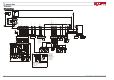
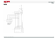
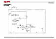


Table Of Contents
- 1169 801 1500
- Vorwort
- Vorwort
- Einleitung
- Sicherheit
- Allgemeine Ansichten
- Verwendung
- Wartung
- Technische Beschreibung
- Vorwort
- Anhang

7 SCHALTPLÄNE
Stromlaufplan
Stromlaufplan
M2
M
_
A2
A1
A
300
F1
K1
-B
+B
26 415
35
9
19 39
10
24
H1
+
-
G1
j
b
bu
v
37
40
25
safety IP4
8
22
A
7.5
F3
1 3 134231 27
temperature M1
21 23229 30
12
Li
24V
diagnostic
14
A1 LAC02B
0V
LH
L
H
24V
0V
0V
0V
114 20187 638
36
2834
24V
0V
1X3
7X6
161533 17
0V
K1
S2
1
4
2
S4
1 2 3 4 5 6 1 2 3 4 5 6
4S1 1S30
A2
X20
1/1
P1
2S80 2S81
P2
0V
1X3
creep
creep speed
portique/mast
belly
Pot tract
pot hyd.
X6
X6
X6
6X2
6X7
1X1
24V
X20:1
S2
A1
A8 B6 B5A5 A6
A2 A3 C2
C3
B3
B4
C1
B1B8
temperature
Can H
Can L
switch AU
0V
X11
1 2 3 412 121 2 3 456 7 8910
12 12
M1
3
UVW
576148912 10 15
16
1311 1 2 4 3
576148912 10 15
16
1311 1 2 4 3
1 2 3 456 7 89101 2 3 4 5 6 1 2 3 4 1 2 3 4 5 6 7
23
emergency button
arret urgence
display can
afficheur
levee de base/initial forks
switch timon/tiller switch
pot. inclinaison/ tiller pot.
capteur vitesse
speed sensor
frein/brake
S4: switch timon
tiller switch
P3: inclinaison timon
tiller potentiometer
tension potentiometre timon vertical
vertical tiller potentiometer value:
(pour info - for information)
X6:3 & 5 = 3.1V
X6:3 & 6 = 0.7V
b: sensor speed 1
bu: sensor speed 2
n
m
b: blanc-white
bu: bleu-blue
g: gris-grey
j: jaune-yellow
m: marron-brown
n: noir-black
r: rouge-red
v: vert-green
bcm n b bcm n b
S6
S5
RC
7X6:7
Lievre/hare
base bas/initial lift bottom
base haute/initial lift top
bouton deverouillage/unlock button
reduction vitesse/speed
detecteur mat/mast sensor
valve portique/mast
valve base/initial lift
valve
valve descente/lowering
contacteur/main contactor
Y6
Y2 Y1
Y5
Y3
+4.3V
bcm n b
S7
1 2 3 4
X11A
2 1
S1
ba
0V
114 Betriebsanleitung – 1169 801 1500 DE – 05/2012