
Instruction Manual


#()!!)$#
"-B0K$#)'$!!'
().%'*)$#
,!#+$!)
Wire feed parts are electrically live while welding and
while inching wire (with Touch Sense feature selection).
The electrically live parts are listed below:
Electrode Electrode Reel
Wire Drive Motor Drive Rolls
Gear Box Cross-seam Adjuster
Wire Straightener Welding Nozzle
Welding Cables Welding Cable Terminal
J> =>C C>D27 4;42CA820;;H ;8E4 ?0ACB >A
4;42CA>34BF8C7H>DAB:8=>AF4C2;>C78=6
J=BD;0C4 H>DAB4;5 5A>< C74 F>A: 0=3
6A>D=3
J;F0HBF40A3AH8=BD;0C8=66;>E4B
"#!/'(
J,4;38=6 58GCDA4 >A F8A4 54434A F8;; <>E4 3DA8=6
F4;38=6 >A 8=278=6 44?0F0H 5A>< ?8=27
?>8=CB
J;42CA>34A44;0=33A8E4A>;;BCDA=3DA8=6
F4;38=6 >A 8=278=6 44? 6;>E43 70=3B
0F0H 5A>< 0A40B C70C <0H 20C27 C74
6;>E4
----------------------------------------------------------------------------------------
!$)$##"$*#)#
The MAXsa™ 10 CONTROLLER will operate in harsh
environments and can be used outdoors with an IP 23
rating. Even so, it is important that simple preventative
measures are followed in order to assure long life and
reliable operation. The MAXsa™ 10 CONTROLLER
must be mounted in the vertical(upright) position and
located where there is little risk of impacts to the
Controller.
!)'($ 20=:8;;
J$=;H 0 @D0;85843 4;42CA8280= B7>D;3
2>==42C C74 "-B0K $#
)'$!!' =BC0;;0C8>= B7>D;3 14
<034 8= 022>A30=24 F8C7 C74
0??A>?A80C4 #0C8>=0; ;42CA820;
>34C74;>20;2>34B0=3C748=5>A
<0C8>=8=C78B<0=D0;
J)DA= >55 C74 8=?DC ?>F4A C> C74
?>F4A B>DA24 0C C74 38B2>==42C
BF8C27 >A 5DB4 1>G 145>A4 F>A:8=6
>= C78B 4@D8?<4=C )DA= >55 C74
8=?DC?>F4AC>0=H>C74A4@D8?<4=C
2>==42C43C>C74F4;38=6BHBC4<0C
C74 38B2>==42C BF8C27 >A 5DB4 1>G
145>A4F>A:8=6>=C78B4@D8?<4=C
J>=>CC>D274;42CA820;;H7>C?0ACB.
----------------------------------------------------------------------------------------
'&*#.%'$))$#
Locate the MAXsa™ 10 CONTROLLER away from radio
controlled machinery. The normal operation of the
MAXsa™ 10 CONTROLLER may adversely affect the
operation of RF controlled equipment, which may result in
bodily injury or damage to the equipment.
*-!'. &*%"#) #%*) %$,'
$##)$#
The MAXsa™ 10 CONTROLLER has the ability to control
auxiliary equipment such as feeders, flux hoppers and
travel motors using solid state relays. There are three
relays (CR1,CR2 &CR3) in the MAXsa™ 10 CON-
TROLLER, controlled by two independent coil drivers. The
coils of CR1 and CR2 are in parallel, therefore, they must
turn ON and OFF at the same time. The CR1 and CR2
relays are designated for driving travel motors to control
motion. CR3 is driven separately, and is designated to
control flux hopper operation.
MAXsa™ 10 CONTROLLER Relay Ratings:
Coil: 12Vdc, resistance = 86 ohms at 25° C
Normally Closed (N.C.) Contacts: 3A @ 277VAC
Normally Open (N.O.) Contacts: 30A @ 277VAC
The MAXsa™ 10 CONTROLLER does not provide the
input power to feed any equipment, other than the MAXsa
22 or the MAXsa 29 feeders. Therefore a separate power
feed must be provided by the end user. The MAXsa™ 10
CONTROLLER has been shipped standard with all of the
wiring and connectivity to operate the Lincoln K325 TC-3
Travel Carriage (4-pin cable connector) and the Lincoln
K219 Automatic Flux Hopper (3-pin cable connector). The
CR2 Relay is wired to the 4-pin travel connector, and the
CR3 Relay is wired to the 3-pin flux connector, both locat-
ed on the bottom of the MAXsa™ 10 CONTROLLER.
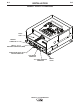
If either of these is to be used with the MAXsa™ 10 CON-
TROLLER, the end-user must provide the 115VAC input
power to the terminal strip located inside the MAXsa™ 10
CONTROLLER. Access to the terminal strip may be
obtained via one of the two .875” dia. (22.2mm) access
holes in the bottom of the MAXsa™ 10 CONTROLLER.
These access holes are shipped with plug buttons
installed. Remove the plug button and install a suitable
strain relief to protect the wires. See Figure A.1
;C7>D678=?DC?>F4AC>"-B0K$#)'$!!'8B
CDA=43>55C742DBC><4A8=BC0;;43 0DG8;80AH 8=?DC<0H
14 4=4A68I43 =BDA4 C70C 0;; 8=?DC ?>F4A C> C74
"-B0K$#)'$!!'8BCDA=43>55145>A4>?4=
8=6C742>E4A
----------------------------------------------------------------------------------------
,'##
,'##
*)$#