RETURN TO MAIN MENU MAXsa 10 CONTROLLER ™ For use with machines having Code Numbers: IM10023-A May, 2011 11590, 11777 Safety Depends on You Lincoln arc welding and cutting equipment is designed and built with safety in mind. However, your overall safety can be increased by proper installation ... and thoughtful operation on your part. DO NOT INSTALL, OPERATE OR REPAIR THIS EQUIPMENT WITHOUT READING THIS MANUAL AND THE SAFETY PRECAUTIONS CONTAINED THROUGHOUT.
i i SAFETY WARNING CALIFORNIA PROPOSITION 65 WARNINGS Diesel engine exhaust and some of its constituents are known to the State of California to cause cancer, birth defects, and other reproductive harm. The Above For Diesel Engines The engine exhaust from this product contains chemicals known to the State of California to cause cancer, birth defects, or other reproductive harm. The Above For Gasoline Engines ARC WELDING CAN BE HAZARDOUS.
ii ii SAFETY ELECTRIC SHOCK can kill. 3.a. The electrode and work (or ground) circuits are electrically “hot” when the welder is on. Do not touch these “hot” parts with your bare skin or wet clothing. Wear dry, hole-free gloves to insulate hands. 3.b. Insulate yourself from work and ground using dry insulation. Make certain the insulation is large enough to cover your full area of physical contact with work and ground.
iii iii SAFETY WELDING and CUTTING SPARKS can cause fire or explosion. 6.a. Remove fire hazards from the welding area. If this is not possible, cover them to prevent the welding sparks from starting a fire. Remember that welding sparks and hot materials from welding can easily go through small cracks and openings to adjacent areas. Avoid welding near hydraulic lines. Have a fire extinguisher readily available. 6.b.
iv SAFETY PRÉCAUTIONS DE SÛRETÉ Pour votre propre protection lire et observer toutes les instructions et les précautions de sûreté specifiques qui parraissent dans ce manuel aussi bien que les précautions de sûreté générales suivantes: Sûreté Pour Soudage A L’Arc 1. Protegez-vous contre la secousse électrique: a. Les circuits à l’électrode et à la piéce sont sous tension quand la machine à souder est en marche.
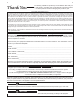
v v Thank You for selecting a QUALITY product by Lincoln Electric. We want you to take pride in operating this Lincoln Electric Company product ••• as much pride as we have in bringing this product to you! CUSTOMER ASSISTANCE POLICY The business of The Lincoln Electric Company is manufacturing and selling high quality welding equipment, consumables, and cutting equipment. Our challenge is to meet the needs of our customers and to exceed their expectations.
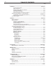
vi vi TABLE OF CONTENTS Page –––––––––––––––––––––––––––––––––––––––––––––––––––––––––––––––––––––––––––––––– Installation.......................................................................................................................Section A Technical Specifications................................................................................................A-1 Safety Precautions ........................................................................................................
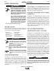
A-1 A-1 INSTALLATION TECHNICAL SPECIFICATIONS: MAXsa™ 10 CONTROLLER INPUT VOLTAGE & CURRENT Model Voltage* K2814-1 40VDC -- Input Amps* 1.0 PHySICAL SIzE• Height 15.0in. (381 mm) Dimensions Width 13.0 in (259 mm) Depth 4.0 in. (102 mm) TEMPERATURE RATING Weight 25 Lbs (11.3 Kg.) * When not driving a motor.
A-2 A-2 INSTALLATION SAFETy PRECAUTION WARNING HIGH FREQUENCy PROTECTION ELECTRIC SHOCK can kill. • Only a qualified electrician should connect the MAXsa™ 10 CONTROLLER. Installation should be made in accordance with the appropriate National Electrical Code, the local codes and the information in this manual. • Turn off the input power to the power source at the disconnect switch or fuse box before working on this equipment.
A-3 A-3 INSTALLATION FIGURE A.
A-4 A-4 INSTALLATION INTERFACING TO THE MAXsa™ 10 CON- Using the Controller as a Hand-held Pendant: TROLLER The MAXsa™ 10 CONTROLLER is a versatile controller. The User Interface can be removed and used as a hand-held pendant. Most circuits can be accessed through the screwless terminal strip. The auxiliary relays can control standard Lincoln equipment, or they can be used to control any other auxiliary equipment custom controls.
A-5 A-5 INSTALLATION Auxiliary Input Power Connection Instructions Use the appropriate size leads, at least 14 AWG – 2 wire with ground. 1. Remove two Phillips Head screws on right side of front panel of hinged door to access terminal strip. 2. Remove a plug button and install a box connector to provide strain relief for the input power leads. 3. Strip off 1/4”(6.4mm) of insulation from the leads and route them through the strain relief 4. Locate the 4-terminal blocks, numbered #48, #49, and #50.
A-6 A-6 INSTALLATION FIGURE A.
A-7 A-7 INSTALLATION 8511 STOP 27 859 START 26 8510 40 SHUTDOWN #2 SUPPLY 25 859 41 SHUTDOWN #1 SUPPLY SHUTDOWN #1 24 GND-C SHUTDOWN INPUTS SWITCH GROUP #1 SUPPLY FLUX GND 23 SHUTDOWN #2 CR3 NC #7 22 CR3-7 Shorting Jumper 39 FIGURE A.5 - SHUTDOWN AND STOP INPUTS Connect STOP Input Here STOP INPUT The MAXsa™ 10 CONTROLLER has two shutdown inputs available on the terminal strip.
A-8 A-8 INSTALLATION FIGURE A.
B-1 OPERATION SAFETy PRECAUTIONS B-1 DESIGN FEATURES Read this entire section of operating instructions before operating the machine. WARNING ELECTRIC SHOCK can kill. • Do not touch electrically live parts or electrodes with your skin or wet clothing. • Insulate yourself from the work and ground. • Always wear dry insulating gloves. • Do not use AC welder if your clothing, gloves or work area is damp or if working on, under or inside workpiece. Use the following equipment: -DC manual (stick) welder.
B-2 B-2 OPERATION GRAPHIC SyMBOLS THAT APPEAR ON THIS MACHINE OR IN THIS MANUAL PENDENT ARCLINK CONNECTOR WIRE FEEDER GENERAL FUNCTIONAL DESCRIPTION • The MAXsa™ 10 CONTROLLER is one of the most versatile user interfaces ever created. Easy to use features make it a snap to adjust the arc for specific preferences. • The user interface brightly displays essential welding information. Use it to quickly adjust weld settings, arc starting parameters, arc end parameters and set-up information.
B-3 B-3 OPERATION FIGURE B.1 - INPUT AND OUTPUT CONNECTIONS STATUS LIGHT PENDANT CONNECTOR MAXsa™ 22 or 29 WIRE DRIVE CONNECTOR (14-PIN) POWER WAVE® AC/DC 1000 SD ARCLINK CONNECTOR FLUX HOPPER CONNECTOR TC-3 TRAVEL CARRIAGE CONNECTOR ACCESS HOLES FIGURE B.
B-4 B-4 OPERATION FIGURE B.4.- FEED CONTROLS FIGURE B.3 - POWER UP 25 ---- MAXsa Initializing. . . ---- Feed Cold Feedhead 1 POWER-UP SEQUENCE SETTING FEED FORWARD/REVERSE When power is first applied to the machine the MODE SELECT Display reads “MAXsa™ Initializing...”. Once the PowerWave AC/DC has intialized (20 to 60 seconds) a “lamp test” is performed. While pressing either the FEED FORWARD or FEED REVERSE pushbutton the MSP Display will read as shown in Figure B.
B-5 B-5 OPERATION CHANGING AND SETTING WELD MODES BALANCE ADjUST To select a weld mode, press the WELD MODE SELECTOR button until the WELD MODE indicator comes ON (it may already be lit by default at power up). Turn the control knob to select the desired mode. After about 1 second, the parameters for the new mode will be displayed. These parameters can be adjusted with the control knobs below each display. Press the WELD MODE selector until the MSP Display reads “Balance”.
B-6 B-6 OPERATION WELD MODE SEARCHING MULTIPLE ARC CONFIGURATION The Weld Mode Search feature allows the selection of a welding mode based on certain criteria (wire size, process type, etc.). Power Wave® AC/DC 1000 SD / MAXsa™ systems can be used in multiple arc set ups with up to six arcs. To minimize magnetic interaction between the arcs, it is imperative that they be phased correctly. Phasing is essentially a time offset between the waveforms of different arcs.
B-7 B-7 OPERATION FGIURE B.6 - WELD SEQUENCE Strike Start Upslope Downslope Crater Burnback Weld Output Arc Start Delay End of Burnback End of Crater Timer End of Downslope Stop Button Pressed End of Upslope End of Start Timer Wire Touches Plate Wire Begins to Feed Start Button Pressed Time WELD SEQUENCE START OPTIONS OPERATION The weld sequence defines the weld procedure from beginning to end. All adjustments are made through the user interface.
B-8 OPERATION END OPTIONS The downslope, crater, and burnback parameters are used to define the end of the weld sequence. The are defined in the following: • DOWNSLOPE determines the amount of time it takes to ramp from the weld parameters to the crater parameters. The transition is linear and may be up or down depending on the relationship between the weld and crater settings. • CRATER parameters are typically used to fill the crater at the end of the weld and include both time and output settings.
B-9 B-9 OPERATION SETUP MENU FEATURES The Setup Menu provides access for configuring user preferences, which are generally only set at installation. The user preferences are grouped as shown in the following table. PARAMETER DEFINITION P.1 through P.99 P.101 through P.199 P.501 through P.599 Unsecured Parameters (always adjustable) Diagnostic Parameters (always read only) Secured Parameters (only accessible with Weld Manager) ACCESSING THE SETUP MENU 1. ACCESS 3.
B-10 OPERATION B-10 USER DEFINED PARAMETERS Parameter Definition Exit Setup Menu P.0 P.1 P.2 P.3 This option is used to exit the setup menu. When P.0 is displayed, press the Left Button to exit the setup menu Wire Feed Speed Units This option selects which units to use for displaying wire feed speed. English = inches/minute wire feed speed units (default). Metric = meters/minute wire feed speed units.
B-11 OPERATION B-11 USER DEFINED PARAMETERS (CONT.) Parameter P.15 Definition Hot-Inch Touch Sense Option This option allows enabling or disabling touch sense when feeding wire forward. Disabled = Touch sensing is disabled when feeding the wire forward (default). Enabled = Touch sensing is active when feeding the wire forward. When enabled and feeding wire forward, the wire is electrically "hot" and waiting to short to the plate.
B-12 OPERATION B-12 USER DEFINED PARAMETERS (CONT.) Parameter P.101 Definition View Event Logs Used for viewing all the system event logs. Press the Right Button to enter the option. Rotate Control Knob to select the desired event log to read. Press the Right Button again to enter the selected log. Rotating the Control Knob will scroll through the event log, displaying the log index number, event code and some other data. Press the Left Button to back out to select another log.
B-13 OPERATION B-13 USER DEFINED PARAMETERS (CONT.) Parameter P.502 Definition Memory Change Lockout Determines if the memories can be overwritten with new contents. No = Memories can be saved and limits can be configured (default). yes = Memories cannot be changed - saving is prohibited and limits cannot be re-configured. This parameter can only be accessed using Power Wave Manager software. P.503 Memory Button Disable Disables the specified memory button(s).
B-14 OPERATION B-14 USER DEFINED PARAMETERS (CONT.) Parameter P.506 Definition Set User Interface Passcode Prevents unauthorized changes to the equipment. The default passcode is zero which allows full access. A nonzero passcode will prevent unauthorized: changes to memory limits, saving to memory (if P.502 = Yes), changes to setup parameters (if P.505 = Yes). This parameter can only be accessed using Power Wave Manager software. P.
B-15 B-15 OPERATION MAKING A WELD Once the necessary parameters have been set and the desired Weld Mode selected: Press the START BUTTON to begin welding. Press the STOP BUTTON to end the weld. The ARC ESTABLISHED INDICATOR will ‘flash’ as the wire feeds towards the work piece to show that OCV is present and switch to ON when the arc is lit. If “Start” parameters have been set they will be in effect for the specified time and then the Weld Mode parameters will take effect.
B-16 OPERATION B-16 USING THE MEMORy OPTION The MAXsa™ 10 has eight available memory locations for storing procedural information. Each location will store the following information: • Weld Mode • Amperage(or WFS) • Voltage MULTI PROCEDURE WELDING The MAXsa™ 10 CONTROLLER can do “On-The-Fly” welding changes with multiple weld procedures by using the Memory Panel.
B-17 B-17 OPERATION SAVING A PROCEDURE TO A MEMORy LOCATION RECALLING A PROCEDURE FROM A MEMORy LOCATION Once the parameters have been set: • Press and Hold the Memory Button of the desired location for 2 seconds. • The LED for that location will come ON. • After 2 seconds the LED will go OFF • The MSP display will show briefly that the information is saved, then return to the Weld Mode. NOTE: Holding the button for longer than 5 seconds will enter the Limits Mode.
B-18 B-18 OPERATION OPTIONAL LIMIT SETUP The Limits feature allows the operator to set minimum and maximum values for various parameters depending on the Weld Mode selected. Set High Limit NOTE: Weld Modes cannot be selected through the Limits Setup Menu. They must be chosen and saved before entering the Limits Menu. SETTING LIMITS 1. Press and hold the desired Memory Button until the LED for that location begins to blink rapidly.
C-1 ACCESSORIES OPTIONS AND ACCESSORIES are available at www.lincolnelectric.com Follow these steps: 1. Go to www.lincolnelectric.com 2. In the Search field type E9.181 and click on the Search icon (or hit ‘Enter’ on the keyboard). 3. On the Results page, scroll down to the Equipment list and click on E9.181. All of the information for the PowerWave System accessories can be found in this document.
D-1 MAINTENANCE SAFETy PRECAUTIONS D-1 ROUTINE MAINTENANCE WARNING ELECTRIC SHOCK can kill. • Do not touch electrically live parts such as output terminals or internal wiring. • Check weld cables, control cables and gas hoses for cuts. PERIODIC MAINTENANCE • N/A • When inching, electrode and drive mechanism are “hot” to work and ground and could remain energized several seconds after the inch button is released. CALIBRATION SPECIFICATION All calibration is factory set on the MAXsa™ 10 CONTROLLER.
E-1 TROUBLESHOOTING E-1 HOW TO USE TROUBLESHOOTING GUIDE WARNING Service and Repair should only be performed by Lincoln Electric Factory Trained Personnel. Unauthorized repairs performed on this equipment may result in danger to the technician and machine operator and will invalidate your factory warranty. For your safety and to avoid Electrical Shock, please observe all safety notes and precautions detailed throughout this manual.
E-2 TROUBLESHOOTING E-2 Observe all Safety Guidelines detailed throughout this manual USING THE STATUS LED TO TROUBLESHOOT SySTEM PROBLEMS The MAXsa 10 is equipped with a Status Light. If a problem occurs it is important to note the condition of the status lights. Therefore, prior to cycling power to the system, check the power source status light for error sequences as noted below.
E-3 E-3 TROUBLESHOOTING Observe all Safety Guidelines detailed throughout this manual PROBLEMS (SyMPTOMS) POSSIBLE CAUSE RECOMMENDED COURSE OF ACTION ARCLINK SySTEM ERROR CODES Err 31 Primary overcurrent 1. The power source has exceeded input current limits. Adjust the welding procedure to reduce the current draw. The welding procedure may exceed the capacity of the power source. 2. See the power source Instruction Manual. Err 32 Capacitor bank "A" under 1. The power source input power voltage.
E-4 E-4 TROUBLESHOOTING Observe all Safety Guidelines detailed throughout this manual PROBLEMS (SyMPTOMS) POSSIBLE CAUSE RECOMMENDED COURSE OF ACTION ARCLINK SySTEM ERROR CODES Err 35 Capacitor bank "B" overvolt- 1. The power source input power age. may be wired incorrectly. Verify the power source reconnect panel wiring matches the input power. 2. See the power source Instruction Manual. Err 36 Thermal 1. Power source overheating. Verify duty cycle is correct.
E-5 E-5 TROUBLESHOOTING Observe all Safety Guidelines detailed throughout this manual PROBLEMS (SyMPTOMS) POSSIBLE CAUSE RECOMMENDED COURSE OF ACTION ARCLINK SySTEM ERROR CODES 1. Verify the earth ground connecErr 44 Main CPU problem. tion to the power source is wired correctly. 2. See the power source Instruction Manual. Err 53 Voltage sense loss. 1. Verify correct sense lead connection. Err 54 Short term secondary overcurrent. Err 81 Motor overload, long term. Err 82 Motor overload, short term.
E-6 E-6 TROUBLESHOOTING Observe all Safety Guidelines detailed throughout this manual PROBLEMS (SyMPTOMS) POSSIBLE CAUSE RECOMMENDED COURSE OF ACTION ARCLINK SySTEM ERROR CODES Err 263 No usable weld modes. 1. The power source does not have any welding programs loaded. If all recommended possible areas of misadjustment have been checked 2. See the power source Instruction and the problem persists, Contact Manual for load welding pro- your local Lincoln Authorized Field grams. Service Facility.
E-7 E-7 TROUBLESHOOTING Typical User Interface 3 digit error codes (not blinked on the status LED). Error Code Source 283 285 612 User Interface UI Text Reason (Varies based on the error type and who caused the error) N/A Internal Error. Collect all displayed values and contact Lincoln Electric Service Department.
E-8 E-8 TROUBLESHOOTING Observe all Safety Guidelines detailed throughout this manual PROBLEMS (SyMPTOMS) POSSIBLE CAUSE RECOMMENDED COURSE OF ACTION OUTPUT PROBLEMS Inconsistent wire feeding or wire not 1. The electrode is rusty or dirty. Use feeding but drive rolls turning. only clean electrode. Use quality electrode, like L-50 or L-56 from Lincoln Electric. 2. The contact tip is partially melted or has spatter. Replace the contact tip. 3. Improper tip, drive rolls and/or inner wire guide.
A B 14-PIN MOTOR MOTOR + RECEPTACLE MOTOR - S3 328C S2 S4 328A 328B S1 N.A. PENDANT CONNECTOR FLUX STOP START AUTO TRAVEL MANUAL L11 L10 846 G TACH 1B DIFF IN N.A.
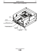
11.68 .20 5.89 12.25 13.25 11.30 MAXsa™ 10 CONTROLLER O .66 O .28 .87 14.40 SCALE = 1 : 4 PENDANT 7.75 7.07 8.90 1.50 L13444 1.
• Do not touch electrically live parts or WARNING Spanish AVISO DE PRECAUCION French ATTENTION German WARNUNG Portuguese ATENÇÃO • Keep flammable materials away. • Wear eye, ear and body protection. • Mantenga el material combustible • Protéjase los ojos, los oídos y el electrode with skin or wet clothing. • Insulate yourself from work and ground. • No toque las partes o los electrodos bajo carga con la piel o ropa mojada. • Aislese del trabajo y de la tierra.
• Keep your head out of fumes. • Use ventilation or exhaust to • Turn power off before servicing. • Do not operate with panel open or guards off. remove fumes from breathing zone. • Los humos fuera de la zona de res- piración. • Mantenga la cabeza fuera de los humos. Utilice ventilación o aspiración para gases. • Gardez la tête à l’écart des fumées. • Utilisez un ventilateur ou un aspira- • Desconectar el cable de ali- mentación de poder de la máquina antes de iniciar cualquier servicio.
• World's Leader in Welding and Cutting Products • • Sales and Service through Subsidiaries and Distributors Worldwide • Cleveland, Ohio 44117-1199 U.S.A. TEL: 216.481.8100 FAX: 216.486.1751 WEB SITE: www.lincolnelectric.