User's Guide
Manuals
Brands
LILEE SYSTEMS Manuals
Electronics
Software defined radio
1
2
3
4
5
6
7
8
9
10
Table Of Contents
Product images
Figure 1: SDR-2400
Figure 2: SM-SDR-2400
Figure 3: LMS-2450-ME-100 chassis with SM-SDR-2400
Contents
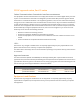
Before You Begin
Safety considerations
ESD notice
FCC/IC approval notice, Part 15 notice
Federal Communications Commission interference statement
15.21:
Approved antennas
Equipment modifications
RF exposure warning
End product labeling
Information for OEMs and integrators
NCC Notice (NCC 警語)
Introduction
Key features
MIMO: Up to 4x4
Worldwide operation
Various modulation and data rates
TDD/TDMA
Cloud-based management
Specifications
Radio interfaces
Physical characteristics
Environmental operating range
Mechanical drawings and dimensions
Top View
Side View (Right)
Front View
Interface Panel and Ports
SM-SDR-2400 front panel view
Antenna ports
LED indicators
LED status light descriptions
MIMO 4x4 mode
MIMO 2x2, all modes (dual, 1/2, or 3/4)
Power (all MIMO 2x2 and 4x4 modes)
Assembly and Installation
Faceplate assembly for SM-SDR-2400
Front panel assembly
Bracket assembly
Connecting RF cables and attaching front panel
Bracket assembly
Cover assembly
Complete assembly
Chassis installation
Smart module installation
Configuring the SDR-2400/SM-SDR-2400
Linking up two units
Base station and client modes
MIMO modes
Pro
duct
im
ages
F
i
gure
1:
S
DR-24
00
F
i
gure
2:
S
M-SD
R-24
00
F
i
gure
3:
L
M
S-2450
-M
E-100
cha
s
s
i
s
wi
th
S
M-SD
R-24
00
S
DR-240
0/SM
-S
D
R-2400
U
s
er
G
u
id
e
Pro
d
uct
imag
e
s
|
3
1
2
3
4
5
...
...
24